LIGHTING LIGHTING SYSTEM(for LED Headlight) Illumination Circuit
DESCRIPTION
The main body ECU receives information regarding the door courtesy switch and door lock position switch, and turns on the map lights and room lights.
- HINT:
-
When the map light switch is in the OFF position, the lights do not illuminate.
WIRING DIAGRAM
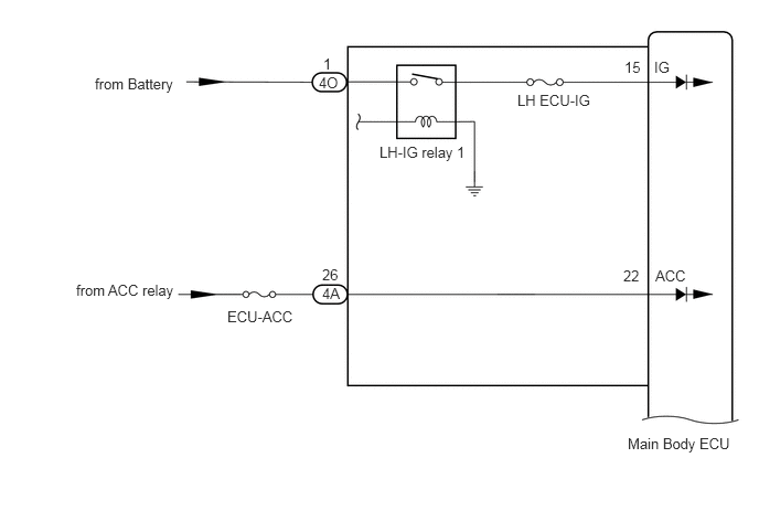
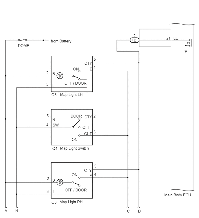
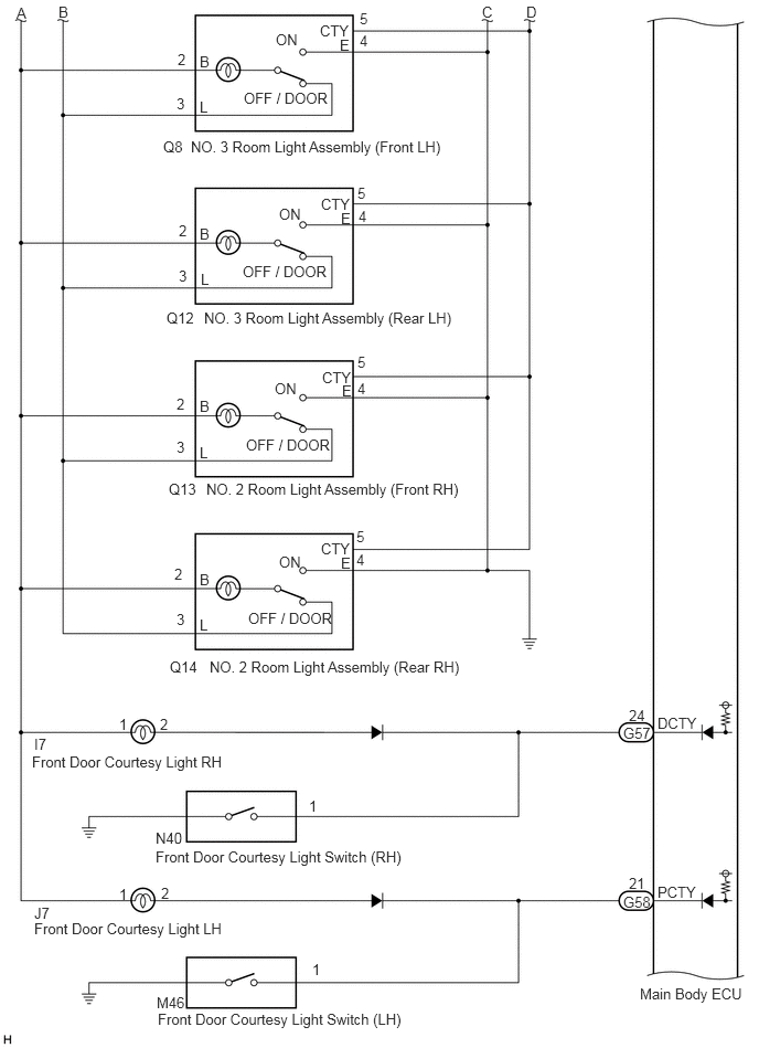
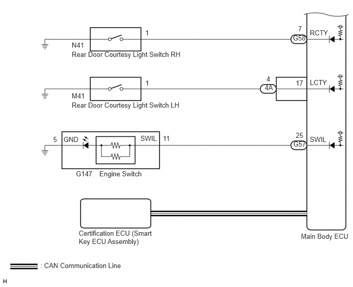
PROCEDURE
Check if the lights controlled by the illuminated entry system illuminate.
| Result | Proceed to |
|---|---|
| Any but not all of the lights that are controlled by the illuminated entry system do not illuminate. | A |
| All of the lights that are controlled by the illuminated entry system do not illuminate. | B |
A
B
Operate each illuminated entry system control function and check for which the malfunction occurs.
| Result | Proceed to |
|---|---|
| Door open/close-linked control function | A |
| Door lock/unlock-linked control function | B |
| Engine switch-linked control function | C |
| Actuation area-linked control function | D |
| Malfunction occurs for all control functions | E |
A
B
C
D
E
Connect the GTS to the DLC3.
Turn the engine switch on (IG).
Turn the GTS on.
Enter the following menus: Body Electrical / Main Body / Data List.
Read the Data List according to the display on the GTS.
| Tester Display | Measurement Item/Range | Normal Condition | Diagnostic Note |
|---|---|---|---|
| D Door Courtesy SW | Front door courtesy light switch RH signal/ON or OFF | ON: Front door RH open
OFF: Front door RH closed |
- |
| P Door Courtesy SW | Front door courtesy light switch LH signal/ON or OFF | ON: Front door LH open
OFF: Front door LH closed |
- |
| RR Door Courtesy SW | Rear door courtesy light switch RH signal/ON or OFF | ON: Rear door RH open
OFF: Rear door RH closed |
- |
| RL Door Courtesy SW | Rear door courtesy light switch LH signal/ON or OFF | ON: Rear door LH open
OFF: Rear door LH closed |
- |
- OK:
Normal condition listed above is displayed.
| Result | Proceed to |
|---|---|
| OK | A |
| NG ("D Door Courtesy SW" or "P Door Courtesy SW" is abnormal) | B |
| NG ("RR Door Courtesy SW" or "RL Door Courtesy SW" is abnormal) | C |
A
B
C
Remove the front door courtesy light switch (See page Vehicle Interior>LIGHTING>FRONT DOOR COURTESY SWITCH>REMOVAL).
Inspect the front door courtesy light switch (See page Vehicle Interior>LIGHTING>FRONT DOOR COURTESY SWITCH>INSPECTION).
| Result | Proceed to |
|---|---|
| OK (for LH side) | A |
| OK (for RH side) | B |
| NG | C |
A
B
C
Disconnect the G58 main body ECU connector.
Measure the resistance according to the value(s) in the table below.
- Standard Resistance:
Tester Connection Condition Specified Condition M46-1 - G58-21 (PCTY) Always Below 1 Ω M46-1 or G58-21 (PCTY) - Body ground Always 10 kΩ or higher
OK
NG
Disconnect the G57 main body ECU connector.
Measure the resistance according to the value(s) in the table below.
- Standard Resistance:
Tester Connection Condition Specified Condition N40-1 - G57-24 (DCTY) Always Below 1 Ω N40-1 or G57-24 (DCTY) - Body ground Always 10 kΩ or higher
OK
NG
Remove the rear door courtesy light switch (See page Vehicle Interior>LIGHTING>REAR DOOR COURTESY SWITCH>REMOVAL).
Inspect the rear door courtesy light switch (See page Vehicle Interior>LIGHTING>REAR DOOR COURTESY SWITCH>INSPECTION).
| Result | Proceed to |
|---|---|
| OK (for LH side) | A |
| OK (for RH side) | B |
| NG | C |
A
B
C
Disconnect the 4A main body ECU connector.
Measure the resistance according to the value(s) in the table below.
- Standard Resistance:
Tester Connection Condition Specified Condition M41-1 - 4A-4 Always Below 1 Ω M41-1 or 4A-4 - Body ground Always 10 kΩ or higher
OK
NG
Disconnect the G58 main body ECU connector.
Measure the resistance according to the value(s) in the table below.
- Standard Resistance:
Tester Connection Condition Specified Condition N41-1 - G58-7 (RCTY) Always Below 1 Ω N41-1 or G58-7 (RCTY) - Body ground Always 10 kΩ or higher
OK
NG
Connect the GTS to the DLC3.
Turn the engine switch on (IG).
Turn the GTS on.
Enter the following menus: Body Electrical / Main Body / Data List.
Read the Data List according to the display on the GTS.
| Tester Display | Measurement Item/Range | Normal Condition | Diagnostic Note |
|---|---|---|---|
| ACC SW | Engine switch ACC signal/ON or OFF | ON: Engine switch on (ACC)
OFF: Engine switch off |
- |
| IG SW | Engine switch IG signal/ON or OFF | ON: Engine switch on (IG)
OFF: Engine switch off |
- |
- OK:
Normal condition listed above is displayed.
| Result | Proceed to |
|---|---|
| OK | A |
| NG ("ACC SW" is abnormal) | B |
| NG ("IG SW" is abnormal) | C |
A
B
C
Disconnect the 4A main body ECU connector.
Measure the voltage of the wire harness side connector.
- Standard Voltage:
Tester Connection Condition Specified Condition 4A-26 - Body ground ACC ON 11 to 14 V
OK
NG
Disconnect the 4O main body ECU connector.
Measure the voltage of the wire harness side connector.
- Standard Voltage:
Tester Connection Condition Specified Condition 4O-1 - Body ground Always 11 to 14 V
OK
NG
Operate the entry unlock function on each door and check that the doors can be unlocked.
- OK:
The entry unlock function operates normally for all doors.
OK
NG
(See pageVehicle Interior>DOOR LOCK>SMART ENTRY AND START SYSTEM>HOW TO PROCEED WITH TROUBLESHOOTING)
Connect the GTS to the DLC3.
Turn the engine switch on (IG).
Turn the GTS on.
Enter the following menus: Body Electrical / Main body / Active Test.
Perform the Active Test according to the display on the GTS.
| Tester Display | Test Part | Control Range | Diagnostic Note |
|---|---|---|---|
| Illuminated Entry System | Interior light illumination | ON / OFF | Map light switch is in DOOR position and all doors are closed |
- OK:
Interior lights illuminate.
OK
NG
Disconnect the 4D main body ECU connector.
Measure the voltage of the wire harness side connector.
- Standard Voltage:
Tester Connection Condition Specified Condition 4D-2 - Body ground Map light switch is in the DOOR position 11 to 14 V
OK
NG