Home › Vehicle Interior › WIPER / WASHER › WIPER AND WASHER SYSTEM
RM24M0E _58 Vehicle Interior _059565 WIPER / WASHER _0291969 WIPER AND WASHER SYSTEM J

WIPER / WASHER  WIPER AND WASHER SYSTEM  Headlight Cleaner Motor and Relay Circuit  


DESCRIPTION

This circuit provides power to the headlight cleaner control relay.

The headlight cleaner control relay receives the signal from the switch, etc., to operate the headlight cleaner motor and pump.

WIRING DIAGRAM
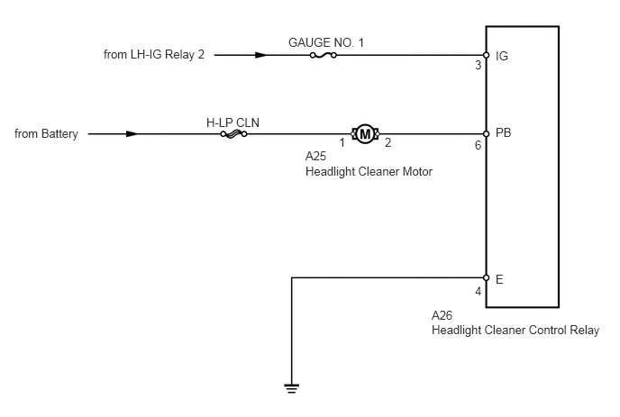
E131998E04
1.198,0.542 2.479,0.813 1.281,0.271 10 false from LH-IG Relay 2 0.167,1.458 1.031,1.625 0.865,0.167 10 false from Battery 2.385,1.333 3.042,1.49 0.656,0.156 10 false H-LP CLN 3.531,1.896 5.063,2.052 1.531,0.156 10 false Headlight Cleaner Motor 3.531,1.719 5.063,1.875 1.531,0.156 10 false A25 3.333,0.406 4.292,0.573 0.958,0.167 10 false GAUGE NO. 1 4.99,3.729 7.052,3.885 2.063,0.156 10 false Headlight Cleaner Control Relay 4.99,3.563 7.052,3.719 2.063,0.156 10 false A26 5.729,0.563 5.917,0.719 0.188,0.156 10 false IG 5.49,0.667 5.677,0.823 0.188,0.156 10 false 3 5.49,1.594 5.677,1.75 0.188,0.156 10 false 6 5.49,3.281 5.677,3.438 0.188,0.156 10 false 4 5.729,1.448 5.969,1.604 0.24,0.156 10 false PB 4.448,1.563 4.688,1.719 0.24,0.156 10 false 2 3.917,1.563 4.156,1.719 0.24,0.156 10 false 1 5.729,3.146 5.969,3.302 0.24,0.156 10 false E

PROCEDURE

1.INSPECT FUSE (GAUGE NO. 1)
a.

Remove the GAUGE NO. 1 fuse from the main body ECU.


b.

Measure the resistance of the fuse.

Standard resistance:

Below 1 Ω


OK

2.CHECK WIRE HARNESS (RELAY - BATTERY AND BODY GROUND)

NG

REPLACE FUSE

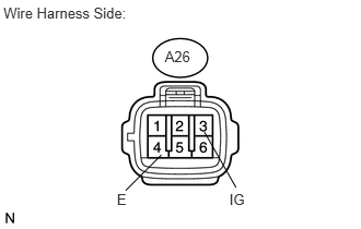
2.CHECK WIRE HARNESS (RELAY - BATTERY AND BODY GROUND)
U189824E01
0.033,0.041 1.499,0.196 1.466,0.156 10 Wire Harness Side: 1.569,0.46 1.863,0.620 0.295,0.161 10 A26 2.184,1.819 2.512,1.965 0.327,0.145 10 IG 1.113,1.819 1.440,1.965 0.327,0.145 10 E 1.945,1.258 2.247,1.791 false 1.197,1.819 1.537,1.479 false

a.

Disconnect the A26 relay connector.


b.

Measure the voltage of the wire harness side connector.

Standard voltage:
Tester Connection Switch Condition Specified Condition
A26-3 (IG) - Body ground Ignition switch on (IG) 10 to 14 V


c.

Measure the resistance of the wire harness side connector.

Standard resistance:
Tester Connection Specified Condition
A26-4 (E) - Body ground Below 1 Ω


OK

3.INSPECT HEADLIGHT CLEANER MOTOR AND PUMP ASSEMBLY

NG

REPAIR OR REPLACE HARNESS OR CONNECTOR

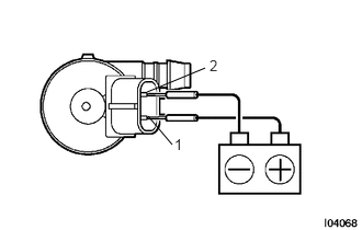
3.INSPECT HEADLIGHT CLEANER MOTOR AND PUMP ASSEMBLY
I004068E03
1.396,0.875 1.948,0.646 false 1.406,1.104 1.635,1.375 false 1.656,1.292 1.75,1.448 0.094,0.156 10 false 1 1.99,0.542 2.083,0.698 0.094,0.156 10 false 2

a.

Remove the headlight cleaner motor.


b.

Apply battery voltage to the headlight cleaner motor and check the operation of the headlight cleaner motor.

OK:
Measurement Condition Specified Condition
Battery positive (+) → Terminal 1
Battery negative (-) → Terminal 2
Headlight cleaner motor operation is normal


OK

4.CHECK WIRE HARNESS (MOTOR - RELAY AND BATTERY)

NG

REPLACE HEADLIGHT CLEANER MOTOR AND PUMP ASSEMBLY

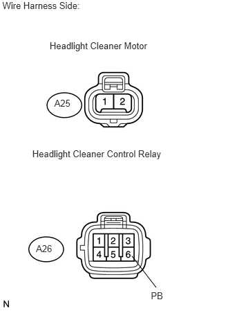
4.CHECK WIRE HARNESS (MOTOR - RELAY AND BATTERY)
U189825E01
0.036,0.001 1.363,0.157 1.327,0.156 10 Wire Harness Side: 0.543,3.652 0.838,3.812 0.295,0.161 10 A26 0.749,0.601 2.288,0.757 1.539,0.156 10 Headlight Cleaner Motor 0.819,1.47 1.114,1.630 0.295,0.161 10 A25 0.487,2.225 2.543,2.388 2.056,0.163 10 Headlight Cleaner Control Relay 2.275,4.365 2.708,4.523 0.434,0.158 10 PB 1.988,3.849 2.353,4.322 false

a.

Disconnect the A25 motor connector.


b.

Disconnect the A26 relay connector.


c.

Measure the voltage of the wire harness side connector.

Standard voltage:
Tester Connection Specified Condition
A25-1 - Body ground 10 to 14 V


d.

Measure the resistance of the wire harness side connectors.

Standard resistance:
Tester Connection Specified Condition
A25-2 - A26-6 (PB) Below 1 Ω
A25-2 - Body ground 10 kΩ or higher


OK

PROCEED TO NEXT CIRCUIT INSPECTION SHOWN IN PROBLEM SYMPTOMS TABLE

NG

REPAIR OR REPLACE HARNESS OR CONNECTOR