Home › Audio / Visual / Telematics › AUDIO / VIDEO › AUDIO AND VISUAL SYSTEM
RM24M0E _56 Audio / Visual / Telematics _059566 AUDIO / VIDEO _0291977 AUDIO AND VISUAL SYSTEM J

AUDIO / VIDEO  AUDIO AND VISUAL SYSTEM  Radio Receiver Communication Error  


PROCEDURE

1.IDENTIFY COMPONENT SHOWN BY THE SUB-CODE
a.

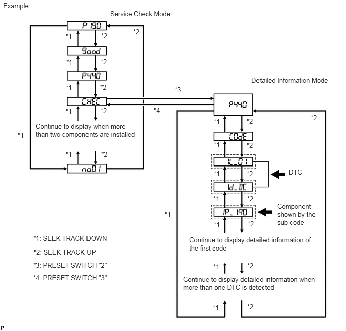
Enter the diagnostic mode.

E110917E28
1.365,0.667 1.635,0.854 0.271,0.188 10 false *1 1.375,1.208 1.646,1.396 0.271,0.188 10 false *1 1.365,1.729 1.635,1.917 0.271,0.188 10 false *1 1.365,2.219 1.635,2.406 0.271,0.188 10 false *1 1.365,3.115 1.635,3.302 0.271,0.188 10 false *1 0.365,2.719 0.635,2.906 0.271,0.188 10 false *1 4.427,2.438 4.698,2.625 0.271,0.188 10 false *1 4.427,2.917 4.698,3.104 0.271,0.188 10 false *1 4.427,3.51 4.698,3.698 0.271,0.188 10 false *1 4.417,4.031 4.688,4.219 0.271,0.188 10 false *1 4.427,4.573 4.698,4.76 0.271,0.188 10 false *1 4.417,5.438 4.688,5.625 0.271,0.188 10 false *1 4.406,6.292 4.677,6.479 0.271,0.188 10 false *1 3.417,4.354 3.688,4.542 0.271,0.188 10 false *1 5.125,5.417 5.396,5.604 0.271,0.188 10 false *2 5.125,6.271 5.396,6.458 0.271,0.188 10 false *2 5.135,4.552 5.406,4.74 0.271,0.188 10 false *2 5.125,4.031 5.396,4.219 0.271,0.188 10 false *2 5.115,3.51 5.385,3.698 0.271,0.188 10 false *2 5.115,2.927 5.385,3.115 0.271,0.188 10 false *2 5.115,2.427 5.385,2.615 0.271,0.188 10 false *2 6.438,2.354 6.708,2.542 0.271,0.188 10 false *2 2.094,3.115 2.365,3.302 0.271,0.188 10 false *2 2.083,2.208 2.354,2.396 0.271,0.188 10 false *2 2.073,1.719 2.344,1.906 0.271,0.188 10 false *2 2.083,1.198 2.354,1.385 0.271,0.188 10 false *2 2.094,0.656 2.365,0.844 0.271,0.188 10 false *2 2.76,0.573 3.031,0.76 0.271,0.188 10 false *2 3.615,1.771 3.885,1.958 0.271,0.188 10 false *3 3.188,2.198 3.458,2.385 0.271,0.188 10 false *4 0.688,4.854 2.313,5.031 1.625,0.177 10 false *1: SEEK TRACK DOWN 0.698,5.135 2.094,5.313 1.396,0.177 10 false *2: SEEK TRACK UP 0.688,5.406 2.323,5.573 1.635,0.167 10 false *3: PRESET SWITCH "2" 0.688,5.667 2.323,5.833 1.635,0.167 10 false *4: PRESET SWITCH "3" 5.979,3.479 6.302,3.646 0.323,0.167 10 false DTC 5.74,4.188 6.719,4.708 0.979,0.521 10 false Component shown by the sub-code 2.281,0.198 3.719,0.375 1.438,0.177 10 false Service Check Mode 5.208,1.583 7,1.76 1.792,0.177 10 false Detailed Information Mode 3.917,4.885 6.49,5.281 2.573,0.396 10 false Continue to display detailed information of the first code 3.792,5.698 6.583,6.104 2.792,0.406 10 false Continue to display detailed information when more than one DTC is detected 0.74,2.531 2.896,2.906 2.156,0.375 10 false Continue to display when more than two components are installed 0.063,0.031 1.052,0.208 0.99,0.177 10 false Example:


b.

Press the preset switch "2" to change to "Detailed Information Mode".


c.

Identify the component shown by the sub-code.

HINT:
·

"190 (radio receiver)" is the component shown by the sub-code in the example shown in the illustration.

·

For details of the DTC display, refer to the "DTC CHECK / CLEAR" (see page Audio / Visual / Telematics>AUDIO / VIDEO>AUDIO AND VISUAL SYSTEM>DTC CHECK / CLEAR).


NEXT

2.CHECK POWER SOURCE CIRCUIT OF COMPONENT SHOWN BY SUB-CODE
a.

Inspect the power source circuit of the component shown by the sub-code.

If the power source circuit is operating normally, proceed to the next step.

Component table
Component Proceed to
Television display assembly (1B0) Television display assembly power source circuit


NEXT

3.INSPECT RADIO RECEIVER ASSEMBLY
a.
U189877E02
1.635,1.49 1.365,1.896 false 1.813,1.49 2.021,1.906 false 0.417,1.146 0.708,1.323 0.292,0.177 10 false F10 1.146,1.917 1.573,2.063 0.427,0.146 10 false TXM- 1.979,1.917 2.406,2.063 0.427,0.146 10 false TXM+

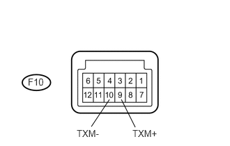
Disconnect the F10 receiver connector.


b.

Measure the resistance of the receiver.

Standard resistance:
Tester Connection Specified Condition
F10-9 (TXM+) - F10-10 (TXM-) 60 to 80 Ω


OK

4.CHECK WIRE HARNESS (RADIO RECEIVER - COMPONENT SHOWN BY SUB-CODE)

NG

REPLACE RADIO RECEIVER ASSEMBLY

4.CHECK WIRE HARNESS (RADIO RECEIVER - COMPONENT SHOWN BY SUB-CODE)
HINT:
·

Start the check from the circuit that is near the component shown by the sub-code first.

·

For details of the connectors, refer to the "Terminals of ECU" (see page Audio / Visual / Telematics>AUDIO / VIDEO>AUDIO AND VISUAL SYSTEM>TERMINALS OF ECU).


a.

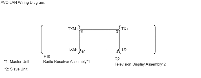
Referring to the AVC-LAN wiring diagram below, check the AVC-LAN circuit between the radio receiver and the component shown by the sub-code.

i.

Check for an open or short in the AVC-LAN circuit between the radio receiver and the component shown by the sub-code.

OK:

There is no open or short circuit.

E130050E04
0.027,0 1.896,0.177 1.869,0.177 10 AVC-LAN Wiring Diagram: 1.539,2.121 3.306,2.284 1.767,0.163 10 Radio Receiver Assembly*1 4.087,2.222 6.035,2.398 1.948,0.177 10 Television Display Assembly*2 2.421,0.946 2.841,1.109 0.420,0.163 10 TXM+ 2.421,1.686 2.841,1.849 0.420,0.163 10 TXM- 4.325,0.946 4.656,1.135 0.331,0.189 10 TX+ 4.325,1.686 4.656,1.875 0.331,0.189 10 TX- 0.147,2.127 1.126,2.314 0.979,0.187 10 *1: Master Unit 0.154,2.401 1.073,2.584 0.920,0.184 10 *2: Slave Unit 1.557,1.944 1.815,2.105 0.258,0.161 10 F10 4.085,2.034 4.408,2.241 0.323,0.207 10 Q21 2.895,1.051 3.215,1.247 0.320,0.195 10 9 4.133,1.048 4.233,1.211 0.100,0.163 10 3 4.143,1.773 4.259,1.942 0.116,0.169 10 4 2.895,1.784 3.188,1.942 0.292,0.158 10 10


OK

5.REPLACE COMPONENT SHOWN BY SUB-CODE

NG

REPAIR OR REPLACE HARNESS OR CONNECTOR

5.REPLACE COMPONENT SHOWN BY SUB-CODE
a.

Replace the component shown by the sub-code with a normal one and check if the same problem occurs again.

OK:

Same problem does not occur.


OK

END

NG

REPLACE RADIO RECEIVER ASSEMBLY