RM24M0E
_56
Audio / Visual / Telematics
_059566
AUDIO / VIDEO
_0291977
AUDIO AND VISUAL SYSTEM
J
AUDIO / VIDEO AUDIO AND VISUAL SYSTEM Television Display Power Source Circuit
DESCRIPTION
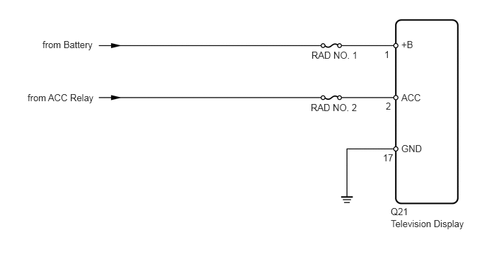
This circuit provides power to the television display.
WIRING DIAGRAM
0.625,0.573 1.781,1.052
1.156,0.479
10
false
from Battery
0.406,1.354 1.719,1.875
1.313,0.521
10
false
from ACC Relay
4.583,0.729 5.344,0.979
0.76,0.25
10
false
RAD NO. 1
4.573,1.5 5.333,1.771
0.76,0.271
10
false
RAD NO. 2
5.906,0.573 6.375,0.802
0.469,0.229
10
false
+B
5.906,1.354 6.479,1.635
0.573,0.281
10
false
ACC
5.906,2.104 6.406,2.354
0.5,0.25
10
false
GND
5.656,0.719 5.906,0.927
0.25,0.208
10
false
1
5.677,1.479 5.979,1.74
0.302,0.26
10
false
2
5.635,2.24 5.885,2.469
0.25,0.229
10
false
17
5.75,3.031 6.156,3.281
0.406,0.25
10
false
Q21
5.75,3.208 6.927,3.49
1.177,0.281
10
false
Television Display
CAUTION / NOTICE / HINT
- NOTICE:
-
Inspect the fuses for circuits related to this system before performing the following inspection procedure.
PROCEDURE
1.CHECK WIRE HARNESS (TELEVISION DISPLAY - BATTERY AND BODY GROUND)
a.
Disconnect the Q21 display connector.
b.
Measure the voltage and resistance of the wire harness side connector.
- Standard voltage:
Tester Connection Condition Specified Condition Q21-1 (+B) - Body ground Always 10 to 14 V Q21-2 (ACC) - Body ground Engine switch on (ACC) 10 to 14 V
- Standard resistance:
Tester Connection Condition Specified Condition Q21-17 (GND) - Body ground Always Below 1 Ω
OK
PROCEED TO NEXT INSPECTION PROCEDURE SHOWN IN PROBLEM SYMPTOMS TABLE
NG
REPAIR OR REPLACE HARNESS OR CONNECTOR