RM24M0E
_56
Audio / Visual / Telematics
_059566
AUDIO / VIDEO
_0291977
AUDIO AND VISUAL SYSTEM
J
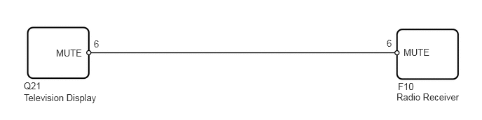
AUDIO / VIDEO AUDIO AND VISUAL SYSTEM Mute Signal Circuit between Radio Receiver and Television Display Assembly
DESCRIPTION
The circuit sends a signal to the television display to mute the noise. Because of this, the noise produced by changing the sound source ceases.
WIRING DIAGRAM
6,0.698 6.51,0.99
0.51,0.292
10
false
MUTE
0.833,0.708 1.344,1
0.51,0.292
10
false
MUTE
0.354,1.375 1.51,1.583
1.156,0.208
10
false
Television Display
5.896,1.365 7.031,1.573
1.135,0.208
10
false
Radio Receiver
0.354,1.198 0.635,1.375
0.281,0.177
10
false
Q21
5.917,1.208 6.177,1.385
0.26,0.177
10
false
F10
5.75,0.563 5.917,0.74
0.167,0.177
10
false
6
1.396,0.573 1.552,0.75
0.156,0.177
10
false
6
PROCEDURE
1.CHECK WIRE HARNESS (RADIO RECEIVER - TELEVISION DISPLAY)
a.
Disconnect the F10 receiver connector.
b.
Disconnect the Q21 display connector.
c.
Measure the resistance of the wire harness side connectors.
- Standard resistance:
Tester Connection Specified Condition F10-6 (MUTE) - Q21-6 (MUTE) Below 1 Ω
OK
2.INSPECT TELEVISION DISPLAY ASSEMBLY
NG
REPAIR OR REPLACE HARNESS OR CONNECTOR
2.INSPECT TELEVISION DISPLAY ASSEMBLY
a.
Replace the television display and check if it operates normally.
- OK:
The television display operates normally.
NG
REPLACE RADIO RECEIVER ASSEMBLY
OK
REPLACE TELEVISION DISPLAY ASSEMBLY