RM24M0E
_58
Vehicle Interior
_059567
SEAT
_0291996
REAR POWER SEAT CONTROL SYSTEM
J
SEAT REAR POWER SEAT CONTROL SYSTEM Park / Neutral Position Switch Circuit
DESCRIPTION
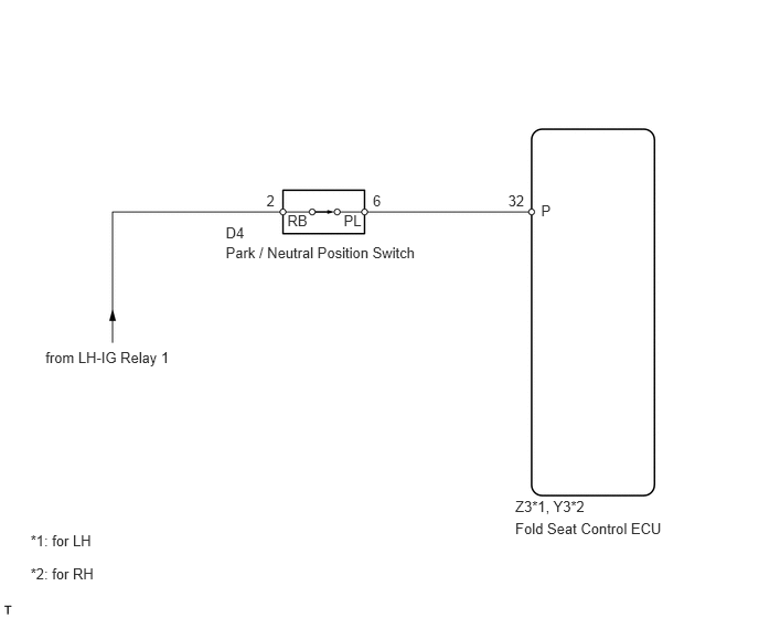
The fold seat control ECU receives signals from the Park / Neutral position switch and controls the seat stowing and return operations. If the shift lever is in any position other than P, the seat cannot be operated. If the ignition switch is on (ACC or IG) the seat cannot be operated.
WIRING DIAGRAM
0.429,3.292 1.836,3.468
1.408,0.177
10
from LH-IG Relay 1
2.713,2.005 2.959,2.210
0.246,0.205
10
RB
3.245,2.005 3.474,2.182
0.229,0.177
10
PL
2.131,2.304 4.023,2.488
1.892,0.184
10
Park / Neutral Position Switch
4.865,4.903 6.348,5.101
1.482,0.198
10
Fold Seat Control ECU
5.109,1.906 5.348,2.090
0.239,0.184
10
P
3.52,1.809 3.760,2.002
0.239,0.193
10
6
0.288,5.025 0.926,5.191
0.638,0.165
10
*1: for LH
0.288,5.334 0.955,5.499
0.668,0.165
10
*2: for RH
2.131,2.115 2.343,2.299
0.211,0.184
10
D4
4.865,4.7 5.564,4.865
0.698,0.165
10
Z3*1, Y3*2
4.798,1.809 4.982,1.993
0.184,0.184
10
32
2.516,1.809 2.639,2.002
0.123,0.193
10
2
PROCEDURE
1.CHECK FOLD SEAT CONTROL ECU (P VOLTAGE)
a.
1.219,1.76 1.563,2.49
false
1.5,2.49 1.646,2.656
0.146,0.167
10
false
P
0.906,0.844 1.083,0.99
0.177,0.146
10
false
Z3
1.063,0.688 1.219,0.875
0.156,0.188
10
false
*1
1.802,0.719 1.958,0.906
0.156,0.188
10
false
*2
0.26,2.625 0.875,2.813
0.615,0.188
10
false
*1: for LH
0.26,3.01 0.917,3.177
0.656,0.167
10
false
*2: for RH
1.563,0.885 1.75,1.042
0.188,0.156
10
false
Y3
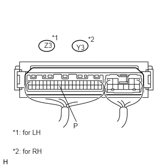
Remove the fold seat control ECU with the connectors still connected.
b.
Turn the ignition switch on (IG).
c.
Measure the voltage of the connector.
- Standard voltage:
- for LH:
Tester Connection Condition Specified Condition Z3-32 (P) - Body ground Park / Neutral position switch P position 10 to 14 V Z3-32 (P) - Body ground Park / Neutral position switch except P position Below 2 V
- for RH:
Tester Connection Condition Specified Condition Y3-32 (P) - Body ground Park / Neutral position switch P position 10 to 14 V Y3-32 (P) - Body ground Park / Neutral position switch except P position Below 2 V
NG
2.INSPECT PARK / NEUTRAL POSITION SWITCH
OK
PROCEED TO NEXT CIRCUIT INSPECTION SHOWN IN PROBLEM SYMPTOMS TABLE
2.INSPECT PARK / NEUTRAL POSITION SWITCH
a.
1.078,2.152 1.315,2.344
0.237,0.192
10
RB
1.638,1.082 1.201,2.143
false
2.113,1.375 2.289,2.143
false
2.19,2.152 2.408,2.338
0.218,0.186
10
PL
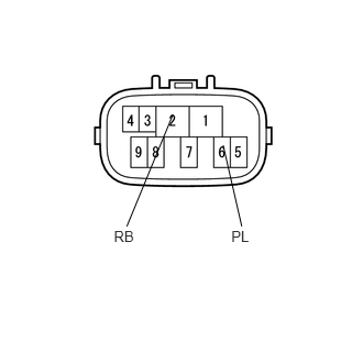
Remove the park / neutral position switch.
b.
Measure the resistance of the switch.
- Standard resistance:
Tester Connection Condition Specified Condition 2 (RB) - 6 (PL) Park / Neutral position switch except P position 10 kΩ or higher 2 (RB) - 6 (PL) Park / Neutral position switch P position Below 1 Ω
OK
3.CHECK WIRE HARNESS (PARK / NEUTRAL POSITION SWITCH - FOLD SEAT CONTROL ECU AND BATTERY)
NG
REPLACE PARK / NEUTRAL POSITION SWITCH
3.CHECK WIRE HARNESS (PARK / NEUTRAL POSITION SWITCH - FOLD SEAT CONTROL ECU AND BATTERY)
a.
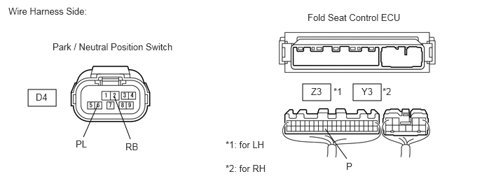
Disconnect the D4 switch connector.
0.417,1.333 0.833,1.583
0.417,0.25
4.5,1.25 4.917,1.5
0.417,0.25
5.25,1.25 5.667,1.5
0.417,0.25
1.24,2.042 1.448,1.573
false
1.938,2.073 1.698,1.438
false
5.156,2.365 4.833,1.917
false
0.125,0.083 1.698,0.417
1.573,0.333
10
false
Wire Harness Side:
0.781,0.615 2.802,0.927
2.021,0.313
10
false
Park / Neutral Position Switch
0.531,1.365 1.479,1.688
0.948,0.323
10
false
D4
1.125,2.063 2.073,2.385
0.948,0.323
10
false
PL
1.865,2.104 2.813,2.427
0.948,0.323
10
false
RB
5.146,2.396 6.094,2.719
0.948,0.323
10
false
P
3.354,2.427 4.323,2.792
0.969,0.365
10
false
*2: for RH
4.625,1.281 5.573,1.604
0.948,0.323
10
false
Z3
4.958,1.281 5.906,1.604
0.948,0.323
10
false
*1
5.375,1.281 6.323,1.604
0.948,0.323
10
false
Y3
5.688,1.281 6.635,1.604
0.948,0.323
10
false
*2
4.573,0.177 6.271,0.49
1.698,0.313
10
false
Fold Seat Control ECU
3.354,2.073 4.323,2.438
0.969,0.365
10
false
*1: for LH
b.
Disconnect the Z3*1 or Y3*2 ECU connector.
c.
Measure the resistance of the wire harness side connectors.
- Standard resistance:
- for LH:
Tester Connection Specified Condition Z3-32 (P) - D4-6 (PL) Below 1 Ω Z3-32 (P) - Body ground 10 kΩ or higher
- for RH:
Tester Connection Specified Condition Y3-32 (P) - D4-6 (PL) Below 1 Ω Y3-32 (P) - Body ground 10 kΩ or higher
d.
Measure the voltage of the wire harness side connector.
- Standard voltage:
Tester Connection Condition Specified Condition D4-2 (RB) - Body ground Ignition switch on (IG) 10 to 14 V D4-2 (RB) - Body ground Ignition switch off Below 1 V
OK
REPLACE FOLD SEAT CONTROL ECU
NG
REPAIR OR REPLACE HARNESS OR CONNECTOR