SEAT REAR POWER SEAT CONTROL SYSTEM Indicator Circuit
DESCRIPTION
This system has 2 indicator lights. One of the indicator lights is built into the fold seat switch. This indicator light receives power from the fold seat control ECU. It comes on or blinks when the system detects that an object is caught or when the seat operation conditions are not met.
The other indicator light is on the combination meter. This indicator light comes on when the reclining motor or fold seat control ECU is not initialized, any seat legs are released, or when the seatback is outside the reclining operation range.
WIRING DIAGRAM
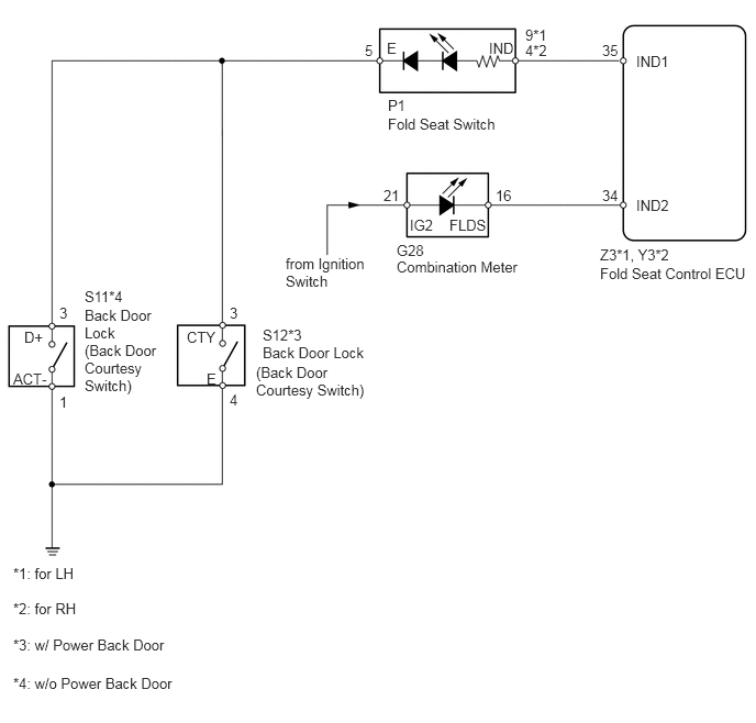
CAUTION / NOTICE / HINT
- HINT:
- ·
When the indicator light on the fold seat switch does not come on, start troubleshooting from "INSPECT FOLD SEAT SWITCH".
·When the indicator light on the combination meter does not come on, start troubleshooting from "INSPECT COMBINATION METER (3RD SEAT INDICATOR LIGHT)".
PROCEDURE
Check the indicator light on the fold seat switch and combination meter.
| Result | Proceed to |
|---|---|
| Indicator light on fold seat switch does not come on | A |
| Indicator light on combination meter does not come on | B |
A
B
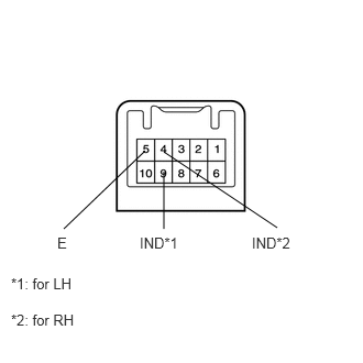
Remove the fold seat switch.
for LH:
Connect the battery's positive (+) lead to terminal 9 (IND) and negative (-) lead to terminal 5 (E), and check that the indicator light comes on.
- OK:
Indicator light comes on.
for RH:
Connect the battery's positive (+) lead to terminal 4 (IND) and negative (-) lead to terminal 5 (E), and check that the indicator light comes on.
- OK:
Indicator light comes on.
OK
NG
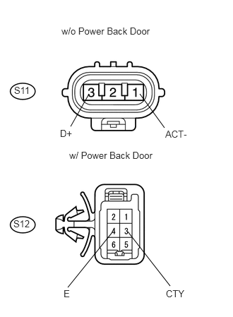
Measure the resistance of the switch.
- Standard resistance:
- w/ Power back door:
Tester Connection Condition Specified Condition S12-3 (CTY) - S12-4 (E) Back door courtesy switch OFF 10 kΩ or higher S12-3 (CTY) - S12-4 (E) Back door courtesy switch ON Below 1 Ω
- w/o Power back door:
Tester Connection Condition Specified Condition S11-3 (D+) - S11-1 (ACT-) Back door courtesy switch OFF 10 kΩ or higher S12-3 (D+) - S11-1 (ACT-) Back door courtesy switch ON Below 1 Ω
OK
NG
Disconnect the P1 switch connector.
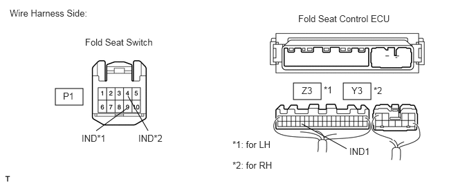
Disconnect the Z3*1 or Y3*2 ECU connector.
Measure the resistance of the wire harness side connectors.
- Standard resistance:
- for LH:
Tester Connection Specified Condition Z3-35 (IND1) - P1-9 (IND) Below 1 Ω Z3-35 (IND1) - Body ground 10 kΩ or higher
- for RH:
Tester Connection Specified Condition Y3-35 (IND1) - P1-4 (IND) Below 1 Ω Y3-35 (IND1) - Body ground 10 kΩ or higher
OK
NG
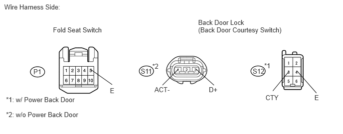
Disconnect the P1 switch connector.
Disconnect the S11*2 or S12*1 lock connector.
Measure the resistance of the wire harness side connectors.
- Standard resistance:
- w/ Power back door:
Tester Connection Specified Condition P1-5 (E) - S12-3 (CTY) Below 1 Ω S12-4 (E) - Body ground Below 1 Ω P1-5 (E) - Body ground 10 kΩ or higher
- w/o Power back door:
Tester Connection Specified Condition P1-5 (E) - S11-3 (D+) Below 1 Ω S11-1 (ACT-) - Body ground Below 1 Ω P1-5 (E) - Body ground 10 kΩ or higher
OK
NG
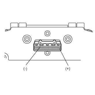
Remove the combination meter.
Connect the battery's positive (+) lead to terminal 21 and negative (-) lead to terminal 16, and check that the indicator light comes on.
- OK:
Indicator light comes on.
OK
NG
Disconnect the Z3*1 or Y3*2 ECU connector.
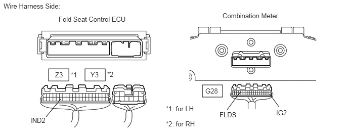
Disconnect the G28 meter connector.
Measure the resistance of the wire harness side connectors.
- Standard resistance:
- for LH:
Tester Connection Specified Condition G28-16 (FLDS) - Z3-34 (IND2) Below 1 Ω G28-16 (FLDS) - Body ground 10 kΩ or higher
- for RH:
Tester Connection Specified Condition G28-16 (FLDS) - Y3-34 (IND2) Below 1 Ω G28-16 (FLDS) - Body ground 10 kΩ or higher
Measure the voltage of the wire harness side connector.
- Standard voltage:
Tester Connection Condition Specified Condition G28-21 (IG2) - Body ground Ignition switch off Below 1 V G28-21 (IG2) - Body ground Ignition switch on (IG) 10 to 14 V
OK
NG