Home › Vehicle Interior › SEAT › REAR POWER SEAT CONTROL SYSTEM › from 2016.05
RM24M0E _58 Vehicle Interior _059567 SEAT _0291996 REAR POWER SEAT CONTROL SYSTEM J

SEAT  REAR POWER SEAT CONTROL SYSTEM  Indicator Circuit  


DESCRIPTION

This system has 2 indicators. One of the indicators is built into the fold seat switch. This indicator receives power from the fold seat control ECU. It comes on or blinks when the system detects that an object is caught or when the seat operation conditions are not met.

The other indicator is on the combination meter. This indicator comes on when the reclining motor or fold seat control ECU is not initialized, any seat leg is released or when the seatback is outside of the reclining operation range.

WIRING DIAGRAM
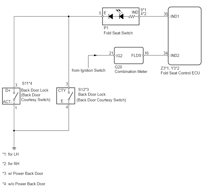
B442623E02
3.646,1.073 4.76,1.271 1.115,0.198 10 false Fold Seat Switch 3.646,0.365 3.854,0.521 0.208,0.156 10 false E 2.135,3.469 2.344,3.625 0.208,0.156 10 false E 4.625,0.344 4.969,0.51 0.344,0.167 10 false IND 5.99,0.49 6.333,0.656 0.344,0.167 10 false IND1 5.99,1.865 6.333,2.031 0.344,0.167 10 false IND2 5.646,2.479 7.083,2.656 1.438,0.177 10 false Fold Seat Control ECU 2.688,3.427 4.979,3.656 2.292,0.229 10 false (Back Door Courtesy Switch) 2.521,2.385 3.76,2.646 1.24,0.26 10 true from Ignition Switch 4.031,2.427 5.25,2.625 1.219,0.198 10 false Combination Meter 2.042,3.094 2.396,3.302 0.354,0.208 10 false CTY 2.75,3.229 3.854,3.458 1.104,0.229 10 false Back Door Lock 0.74,3.083 1.948,3.771 1.208,0.688 10 false Back Door Lock (Back Door Courtesy Switch) 2.75,3.063 3.26,3.229 0.51,0.167 10 false S12*3 0.771,2.844 1.302,3.01 0.531,0.167 10 false S11*4 4.938,0.26 5.188,0.458 0.25,0.198 10 false 9*1 4.938,0.396 5.24,0.583 0.302,0.188 10 false 4*2 3.479,0.375 3.604,0.563 0.125,0.188 10 false 5 3.646,0.896 3.844,1.052 0.198,0.156 10 false P1 4.031,2.271 4.323,2.5 0.292,0.229 10 false G28 5.646,2.313 6.344,2.49 0.698,0.177 10 false Z3*1, Y3*2 0.083,5.333 0.698,5.479 0.615,0.146 10 false *1: for LH 0.083,5.667 0.74,5.813 0.656,0.146 10 false *2: for RH 0.083,6.375 1.865,6.521 1.781,0.146 10 false *4: w/o Power Back Door 0.083,6.01 1.792,6.188 1.708,0.177 10 false *3: w/ Power Back Door 0.188,3.094 0.417,3.292 0.229,0.198 10 false D+ 0.104,3.49 0.479,3.677 0.375,0.188 10 false ACT- 5.75,0.406 5.948,0.635 0.198,0.229 10 false 35 5.74,1.781 5.938,1.99 0.198,0.208 10 false 34 2.313,2.865 2.479,3.052 0.167,0.188 10 false 3 2.313,3.677 2.469,3.875 0.156,0.198 10 false 4 0.531,2.906 0.698,3.094 0.167,0.188 10 false 3 0.521,3.708 0.625,3.938 0.104,0.229 10 false 1 3.833,1.781 4.021,2.031 0.188,0.25 10 false 21 5.073,1.781 5.323,2.031 0.25,0.25 10 false 16 4.615,1.865 5.052,2.094 0.438,0.229 10 false FLDS 4.083,1.875 4.396,2.063 0.313,0.188 10 false IG2

CAUTION / NOTICE / HINT

HINT:
·

When the indicator light on the fold seat switch does not come on, start troubleshooting from "INSPECT FOLD SEAT SWITCH".

·

When the indicator light on the combination meter does not come on, start troubleshooting from "INSPECT COMBINATION METER (3RD SEAT INDICATOR LIGHT)".


PROCEDURE

1.CHECK INDICATOR LIGHT
a.

Check the indicator light on the fold seat switch and combination meter.

Result
Result Proceed to
Indicator light on fold seat switch does not come on A
Indicator light on combination meter does not come on (for LHD) B
Indicator light on combination meter does not come on (for RHD) C


A

2.INSPECT FOLD SEAT SWITCH

B

6.INSPECT COMBINATION METER (3RD SEAT INDICATOR LIGHT)

C

7.CHECK WIRE HARNESS (COMBINATION METER - FOLD SEAT CONTROL ECU AND BATTERY)
2.INSPECT FOLD SEAT SWITCH
a.
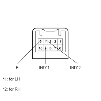
B141308E02
2.63,2.159 1.555,1.351 false 0.102,2.605 0.718,2.811 0.615,0.206 10 *1: for LH 0.102,2.944 0.751,3.132 0.648,0.188 10 *2: for RH 1.391,1.35 0.599,2.171 false 1.555,1.578 1.554,2.17 false 0.539,2.22 0.666,2.394 0.127,0.174 10 E 1.324,2.22 1.720,2.409 0.396,0.190 10 IND*1 2.383,2.22 2.794,2.429 0.411,0.209 10 IND*2

Remove the fold seat switch.


b.

for LH:

Connect the battery's positive (+) lead to terminal 9 (IND) and negative (-) lead to terminal 5 (E), and check that the indicator light comes on.

OK:

Indicator light comes on.


c.

for RH:

Connect the battery's positive (+) lead to terminal 4 (IND) and negative (-) lead to terminal 5 (E), and check that the indicator light comes on.

OK:

Indicator light comes on.


OK

3.INSPECT BACK DOOR LOCK (BACK DOOR COURTESY SWITCH)

NG

REPLACE FOLD SEAT SWITCH

3.INSPECT BACK DOOR LOCK (BACK DOOR COURTESY SWITCH)
a.
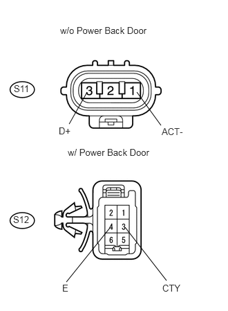
U188703E02
1.313,1.385 1.042,1.865 false 2.063,1.385 2.427,1.885 false 1.885,3.417 2.51,4.219 false 1.656,3.427 1,4.24 false 1.021,2.208 2.333,2.406 1.313,0.198 10 false w/ Power Back Door 0.906,0.375 2.344,0.573 1.438,0.198 10 false w/o Power Back Door 0.885,1.885 1.135,2.104 0.25,0.219 10 false D+ 2.438,1.896 2.875,2.125 0.438,0.229 10 false ACT- 2.448,4.25 2.781,4.469 0.333,0.219 10 false CTY 0.938,4.25 1.083,4.438 0.146,0.188 10 false E 0.208,1.25 0.531,1.438 0.323,0.188 10 false S11 0.198,3.219 0.521,3.406 0.323,0.188 10 false S12

Measure the resistance of the switch.

Standard resistance:
w/ Power back door:
Tester Connection Condition Specified Condition
S12-3 (CTY) - S12-4 (E) Back door courtesy switch OFF 10 kΩ or higher
S12-3 (CTY) - S12-4 (E) Back door courtesy switch ON Below 1 Ω

w/o Power back door:
Tester Connection Condition Specified Condition
S11-3 (D+) - S11-1 (ACT-) Back door courtesy switch OFF 10 kΩ or higher
S12-3 (D+) - S11-1 (ACT-) Back door courtesy switch ON Below 1 Ω


OK

4.CHECK WIRE HARNESS (FOLD SEAT CONTROL ECU - FOLD SEAT SWITCH)

NG

REPLACE BACK DOOR LOCK

4.CHECK WIRE HARNESS (FOLD SEAT CONTROL ECU - FOLD SEAT SWITCH)
a.

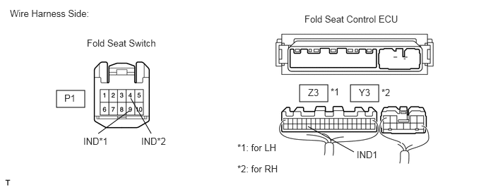
Disconnect the P1 switch connector.

B460042E01
0.833,1.333 1.25,1.583 0.417,0.25 4.417,1.25 4.833,1.5 0.417,0.25 5.167,1.25 5.583,1.5 0.417,0.25 1.448,1.969 1.906,1.635 false 2.229,1.969 1.927,1.448 false 5.219,2.24 4.542,1.865 false 0.146,0.115 1.604,0.427 1.458,0.313 10 false Wire Harness Side: 1.281,0.552 2.469,0.813 1.188,0.26 10 false Fold Seat Switch 0.948,1.365 1.625,1.667 0.677,0.302 10 false P1 1.229,2 1.906,2.302 0.677,0.302 10 false IND*1 2.083,2 2.76,2.302 0.677,0.302 10 false IND*2 4.49,0.198 6.396,0.563 1.906,0.365 10 false Fold Seat Control ECU 4.542,1.281 5.219,1.583 0.677,0.302 10 false Z3 4.875,1.271 5.552,1.573 0.677,0.302 10 false *1 5.292,1.281 5.969,1.583 0.677,0.302 10 false Y3 5.625,1.281 6.302,1.583 0.677,0.302 10 false *2 5.26,2.198 5.938,2.5 0.677,0.302 10 false IND1 3.5,2.406 4.313,2.792 0.813,0.385 10 false *2: for RH 3.5,2.094 4.313,2.479 0.813,0.385 10 false *1: for LH


b.

Disconnect the Z3*1 or Y3*2 ECU connector.

c.

Measure the resistance of the wire harness side connectors.

Standard resistance:
for LH:
Tester Connection Specified Condition
Z3-35 (IND1) - P1-9 (IND) Below 1 Ω
Z3-35 (IND1) - Body ground 10 kΩ or higher

for RH:
Tester Connection Specified Condition
Y3-35 (IND1) - P1-4 (IND) Below 1 Ω
Y3-35 (IND1) - Body ground 10 kΩ or higher


OK

5.CHECK WIRE HARNESS (FOLD SEAT SWITCH AND BODY GROUND - BACK DOOR COURTESY SWITCH)

NG

REPAIR OR REPLACE HARNESS OR CONNECTOR

5.CHECK WIRE HARNESS (FOLD SEAT SWITCH AND BODY GROUND - BACK DOOR COURTESY SWITCH)
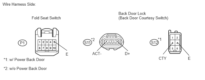
U188723E01
0.089,0.066 1.528,0.252 1.438,0.186 10 Wire Harness Side: 1.108,0.538 2.207,0.752 1.099,0.214 10 Fold Seat Switch 0.699,1.413 0.895,1.561 0.195,0.148 10 P1 2.297,1.811 2.463,1.977 0.166,0.166 10 E 4.093,1.442 4.471,1.781 false 4.141,0.538 5.970,0.722 1.829,0.184 10 (Back Door Courtesy Switch) 1.897,1.453 2.343,1.769 false 6.037,1.491 5.7,1.901 false 4.364,1.79 4.596,1.960 0.232,0.170 10 D+ 5.547,1.958 5.905,2.114 0.357,0.156 10 CTY 2.941,1.404 3.292,1.612 0.350,0.208 10 S11 3.182,1.303 3.402,1.514 0.221,0.211 10 *2 5.281,1.404 5.632,1.612 0.350,0.208 10 S12 5.521,1.291 5.742,1.502 0.221,0.211 10 *1 0.127,2.003 1.837,2.243 1.711,0.239 10 *1: w/ Power Back Door 0.127,2.317 1.921,2.477 1.795,0.160 10 *2: w/o Power Back Door 4.141,0.383 5.160,0.560 1.019,0.177 10 Back Door Lock 6.206,1.483 6.611,1.945 false 3.73,1.442 3.394,1.781 false 3.228,1.79 3.593,2.001 0.364,0.211 10 ACT- 6.57,1.958 6.736,2.124 0.166,0.166 10 E

a.

Disconnect the P1 switch connector.


b.

Disconnect the S11*2 or S12*1 lock connector.


c.

Measure the resistance of the wire harness side connectors.

Standard resistance:
w/ Power back door:
Tester Connection Specified Condition
P1-5 (E) - S12-3 (CTY) Below 1 Ω
S12-4 (E) - Body ground Below 1 Ω
P1-5 (E) - Body ground 10 kΩ or higher

w/o Power back door:
Tester Connection Specified Condition
P1-5 (E) - S11-3 (D+) Below 1 Ω
S11-1 (ACT-) - Body ground Below 1 Ω
P1-5 (E) - Body ground 10 kΩ or higher


OK

6.INSPECT COMBINATION METER (3RD SEAT INDICATOR LIGHT)

NG

REPAIR OR REPLACE HARNESS OR CONNECTOR

6.INSPECT COMBINATION METER (3RD SEAT INDICATOR LIGHT)
a.
B142287E02
2.146,1.75 2.469,2.375 false 1.458,1.688 0.938,2.354 false 0.844,2.396 1.01,2.604 0.167,0.208 10 false (-) 2.365,2.396 2.563,2.604 0.198,0.208 10 false (+)

Remove the combination meter.


b.

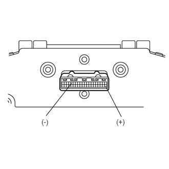
Connect the battery's positive (+) lead to terminal 21 and negative (-) lead to terminal 16, and check that the indicator light comes on.

OK:

Indicator light comes on.


OK

7.CHECK WIRE HARNESS (COMBINATION METER - FOLD SEAT CONTROL ECU AND BATTERY)

NG

REPLACE COMBINATION METER

7.CHECK WIRE HARNESS (COMBINATION METER - FOLD SEAT CONTROL ECU AND BATTERY)
a.

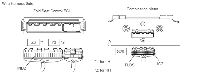
Disconnect the Z3*1 or Y3*2 ECU connector.

B460053E01
1,1.417 1.417,1.667 0.417,0.25 1.75,1.417 2.167,1.667 0.417,0.25 4.167,1.75 4.583,2 0.417,0.25 0.948,2.406 1.25,2.042 false 4.677,2.26 4.958,1.885 false 5.75,2.208 5.552,1.938 false 0.073,0.042 1.344,0.302 1.271,0.26 10 false Wire Harness Side: 1.208,0.313 2.979,0.635 1.771,0.323 10 false Fold Seat Control ECU 1.135,1.458 1.646,1.698 0.51,0.24 10 false Z3 1.458,1.458 1.969,1.698 0.51,0.24 10 false *1 1.865,1.458 2.375,1.698 0.51,0.24 10 false Y3 2.208,1.448 2.719,1.688 0.51,0.24 10 false *2 0.625,2.396 1.135,2.635 0.51,0.24 10 false IND2 4.583,0.24 6.031,0.51 1.448,0.271 10 false Combination Meter 4.229,1.792 4.74,2.031 0.51,0.24 10 false G28 4.521,2.281 5.031,2.521 0.51,0.24 10 false FLDS 5.688,2.24 6.198,2.479 0.51,0.24 10 false IG2 3.417,2.469 4.24,2.792 0.823,0.323 10 false *2: for RH 3.417,2.156 4.24,2.479 0.823,0.323 10 false *1: for LH


b.

Disconnect the G28 meter connector.


c.

Measure the resistance of the wire harness side connectors.

Standard resistance:
for LH:
Tester Connection Specified Condition
G28-16 (FLDS) - Z3-34 (IND2) Below 1 Ω
G28-16 (FLDS) - Body ground 10 kΩ or higher

for RH:
Tester Connection Specified Condition
G28-16 (FLDS) - Y3-34 (IND2) Below 1 Ω
G28-16 (FLDS) - Body ground 10 kΩ or higher


d.

Measure the voltage of the wire harness side connector.

Standard voltage:
Tester Connection Condition Specified Condition
G28-21 (IG2) - Body ground Ignition switch off Below 1 V
G28-21 (IG2) - Body ground Ignition switch on (IG) 10 to 14 V


OK

PROCEED TO NEXT CIRCUIT INSPECTION SHOWN IN PROBLEM SYMPTOMS TABLE

NG

REPAIR OR REPLACE HARNESS OR CONNECTOR