RM24M0E
_58
Vehicle Interior
_059567
SEAT
_0291996
REAR POWER SEAT CONTROL SYSTEM
J
SEAT REAR POWER SEAT CONTROL SYSTEM Power Source Circuit
DESCRIPTION
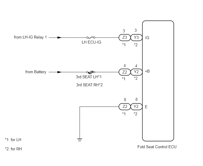
Power is supplied to the fold seat control ECU through the LH ECU-IG fuse, and 3RD SEAT LH and 3RD SEAT RH H-fuses.
WIRING DIAGRAM
4.854,5.073 6.313,5.271
1.458,0.198
10
false
Fold Seat Control ECU
5.125,1.24 5.396,1.49
0.271,0.25
10
false
IG
5.115,2.417 5.333,2.635
0.219,0.219
10
false
+B
5.115,3.667 5.26,3.854
0.146,0.188
10
false
E
4.729,1.229 4.938,1.375
0.208,0.146
10
false
Y3
4.75,0.979 4.927,1.208
0.177,0.229
10
false
3
4.729,1.49 4.927,1.688
0.198,0.198
10
false
*2
4.729,2.438 4.927,2.604
0.198,0.167
10
false
Y2
4.719,3.656 4.927,3.802
0.208,0.146
10
false
Y2
4.771,2.229 4.958,2.375
0.188,0.146
10
false
4
4.781,3.406 4.948,3.573
0.167,0.167
10
false
8
4.729,2.667 4.917,2.854
0.188,0.188
10
false
*2
4.719,3.917 4.927,4.104
0.208,0.188
10
false
*2
4.323,1.229 4.521,1.385
0.198,0.156
10
false
Z3
4.333,1 4.51,1.229
0.177,0.229
10
false
3
4.313,1.49 4.542,1.688
0.229,0.198
10
false
*1
4.323,2.448 4.521,2.615
0.198,0.167
10
false
Z2
4.333,3.656 4.531,3.823
0.198,0.167
10
false
Z2
4.365,2.219 4.552,2.365
0.188,0.146
10
false
4
4.375,3.417 4.542,3.583
0.167,0.167
10
false
8
4.302,2.688 4.5,2.865
0.198,0.177
10
false
*1
4.313,3.917 4.49,4.146
0.177,0.229
10
false
*1
2.885,1.396 3.688,1.573
0.802,0.177
10
false
LH ECU-IG
0.49,1.219 1.885,1.417
1.396,0.198
10
false
from LH-IG Relay 1
0.896,2.438 1.781,2.625
0.885,0.188
10
false
from Battery
2.677,2.615 3.906,2.813
1.229,0.198
10
false
3rd SEAT LH*1
2.688,2.896 3.813,3.094
1.125,0.198
10
false
3rd SEAT RH*2
0.177,4.823 0.906,5.031
0.729,0.208
10
false
*1: for LH
0.177,5.146 0.823,5.333
0.646,0.188
10
false
*2: for RH
PROCEDURE
1.INSPECT FUSE (LH ECU-IG, 3RD SEAT LH, 3RD SEAT RH)
a.
Remove the LH ECU-IG fuse from the instrument panel junction block LH.
b.
Remove the 3RD SEAT LH and 3RD SEAT RH H-fuses from the fusible link block.
c.
Measure the resistance of the fuses.
- Standard resistance:
Below 1 Ω
OK
2.CHECK WIRE HARNESS (FOLD SEAT CONTROL ECU - BATTERY AND BODY GROUND)
NG
REPLACE FUSE
2.CHECK WIRE HARNESS (FOLD SEAT CONTROL ECU - BATTERY AND BODY GROUND)
a.
1.865,2.208 0.281,2.552
false
2.542,2.292 3.063,2.521
false
2.292,2.177 2.125,2.563
false
0.042,0 1.438,0.177
1.396,0.177
10
false
Wire Harness Side:
0.104,2.479 0.313,2.646
0.208,0.167
10
false
IG
3.125,2.479 3.271,2.656
0.146,0.177
10
false
E
0.844,1.719 1.156,1.917
0.313,0.198
10
false
Z3
1.479,1.729 1.771,1.896
0.292,0.167
10
false
Y3
2.198,1.719 2.469,1.885
0.271,0.167
10
false
Z2
2.833,1.719 3.125,1.906
0.292,0.188
10
false
Y2
2.458,1.646 2.646,1.802
0.188,0.156
10
false
*1
3.125,1.646 3.302,1.792
0.177,0.146
10
false
*2
1.125,1.677 1.313,1.833
0.188,0.156
10
false
*1
1.781,1.677 1.958,1.823
0.177,0.146
10
false
*2
0.292,2.875 0.906,3.083
0.615,0.208
10
false
*1: for LH
0.292,3.125 0.948,3.313
0.656,0.188
10
false
*2: for RH
2,2.604 2.208,2.802
0.208,0.198
10
false
+B
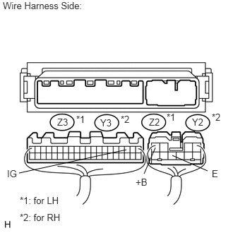
Disconnect the Z2*1 and Z3*1, or Y2*2 and Y3*2 ECU connectors.
b.
Measure the voltage of the wire harness side connectors.
- Standard voltage:
- for LH:
Tester Connection Condition Specified Condition Z3-3 (IG) - Body ground Ignition switch off Below 1 V Z3-3 (IG) - Body ground Ignition switch on (IG) 10 to 14 V Z2-4 (+B) - Body ground Always 10 to 14 V
- for RH:
Tester Connection Condition Specified Condition Y3-3 (IG) - Body ground Ignition switch off Below 1 V Y3-3 (IG) - Body ground Ignition switch on (IG) 10 to 14 V Y2-4 (+B) - Body ground Always 10 to 14 V
c.
Measure the resistance of the wire harness side connector.
- Standard resistance:
- for LH:
Tester Connection Specified Condition Z2-8 (E) - Body ground Below 1 Ω
- for RH:
Tester Connection Specified Condition Y2-8 (E) - Body ground Below 1 Ω
OK
PROCEED TO NEXT CIRCUIT INSPECTION SHOWN IN PROBLEM SYMPTOMS TABLE
NG
REPAIR OR REPLACE HARNESS OR CONNECTOR