Home › Vehicle Interior › SEAT › REAR POWER SEAT CONTROL SYSTEM › from 2016.05
RM24M0E _58 Vehicle Interior _059567 SEAT _0291996 REAR POWER SEAT CONTROL SYSTEM J

SEAT  REAR POWER SEAT CONTROL SYSTEM  Lock Switch Circuit  


DESCRIPTION

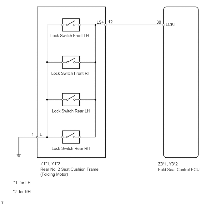
The left and right seats each have lock switches that detect the lock condition of the seat legs to the floor when the seat is in the original or folded-down state. If any of the lock switches detect an unlock condition, he 3rd seat indicator on the combination meter will come on and the folding-down, return and reclining operations will be disabled.

WIRING DIAGRAM
B148161E02
1.344,5.573 3.385,5.906 2.042,0.333 10 false Rear No. 2 Seat Cushion Frame (Folding Motor) 3.219,0.656 3.49,0.802 0.271,0.146 10 false LS+ 5.521,0.729 5.938,0.875 0.417,0.146 10 false LCKF 1.677,1.104 3.073,1.302 1.396,0.198 10 false Lock Switch Front LH 1.708,2.365 3.104,2.563 1.396,0.198 10 false Lock Switch Front RH 1.729,3.625 3.125,3.823 1.396,0.198 10 false Lock Switch Rear LH 1.719,4.875 3.115,5.073 1.396,0.198 10 false Lock Switch Rear RH 5.271,5.583 6.76,5.74 1.49,0.156 10 false Fold Seat Control ECU 1.323,4.406 1.51,4.573 0.188,0.167 10 false E 3.604,0.646 3.781,0.813 0.177,0.167 10 false 12 5.219,0.656 5.396,0.813 0.177,0.156 10 false 38 1.052,4.417 1.208,4.646 0.156,0.229 10 false 1 0.448,6.021 1.052,6.25 0.604,0.229 10 false *1: for LH 0.427,6.323 1.052,6.552 0.625,0.229 10 false *2: for RH 1.354,5.385 2.063,5.573 0.708,0.188 10 false Z1*1, Y1*2 5.271,5.396 5.958,5.573 0.688,0.177 10 false Z3*1, Y3*2

PROCEDURE

1.CHECK FOLD SEAT CONTROL ECU (LCKF VOLTAGE)
a.
U188622E02
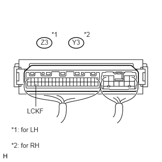
0.76,1.781 0.76,2.26 false 0.573,2.271 0.969,2.438 0.396,0.167 10 false LCKF 1.531,0.813 1.844,0.969 0.313,0.156 10 false Y3 0.865,0.813 1.135,0.958 0.271,0.146 10 false Z3 1.094,0.646 1.281,0.813 0.188,0.167 10 false *1 1.781,0.646 1.979,0.885 0.198,0.24 10 false *2 0.24,2.667 0.844,2.875 0.604,0.208 10 false *1: for LH 0.24,3 0.875,3.188 0.635,0.188 10 false *2: for RH

Remove the fold seat control ECU with the connector still connected.


b.

Measure the voltage of the wire harness side connector.

Standard voltage:
for LH:
Tester Connection Condition Specified Condition
Z3-38 (LCKF) - Body ground Any of the lock switches UNLOCK Below 1 V
Z3-38 (LCKF) - Body ground All lock switches LOCK 10 to 14 V

for RH:
Tester Connection Condition Specified Condition
Y3-38 (LCKF) - Body ground Any of the lock switches UNLOCK Below 1 V
Y3-38 (LCKF) - Body ground All lock switches LOCK 10 to 14 V


NG

2.CHECK WIRE HARNESS (LOCK SWITCH - FOLD SEAT CONTROL ECU AND BODY GROUND)

OK

PROCEED TO NEXT CIRCUIT INSPECTION SHOWN IN PROBLEM SYMPTOMS TABLE

2.CHECK WIRE HARNESS (LOCK SWITCH - FOLD SEAT CONTROL ECU AND BODY GROUND)
a.

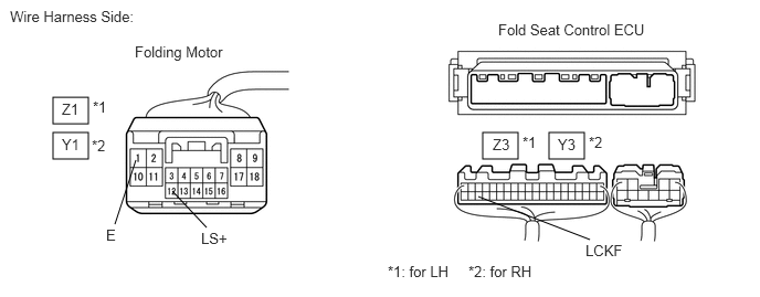
Disconnect the Z1*1 or Y1*2 switch connector.
B460076E02
0.5,0.917 0.833,1.167 0.333,0.25 0.5,1.25 0.833,1.5 0.333,0.25 4.552,1.25 4.885,1.5 0.333,0.25 5.177,1.25 5.51,1.5 0.333,0.25 1.083,2.115 1.281,1.51 false 1.625,1.802 1.948,2.146 false 5.563,2.26 4.51,1.854 false 0.094,0.073 1.427,0.281 1.333,0.208 10 false Wire Harness Side: 1.271,0.406 2.302,0.635 1.031,0.229 10 false Folding Motor 0.583,0.948 0.99,1.198 0.406,0.25 10 false Z1 0.875,0.927 1.281,1.177 0.406,0.25 10 false *1 0.583,1.281 0.99,1.531 0.406,0.25 10 false Y1 0.865,1.292 1.271,1.542 0.406,0.25 10 false *2 1,2.135 1.406,2.385 0.406,0.25 10 false E 1.896,2.167 2.302,2.417 0.406,0.25 10 false LS+ 4.646,1.281 5.052,1.531 0.406,0.25 10 false Z3 5.26,1.281 5.667,1.531 0.406,0.25 10 false Y3 5.521,2.281 6.292,2.479 0.771,0.198 10 false LCKF 4.417,2.479 5.083,2.792 0.667,0.313 10 false *2: for RH 4.698,0.198 6.365,0.479 1.667,0.281 10 false Fold Seat Control ECU 4.927,1.26 5.333,1.51 0.406,0.25 10 false *1 5.552,1.26 5.958,1.51 0.406,0.25 10 false *2 3.656,2.479 4.323,2.792 0.667,0.313 10 false *1: for LH


b.

Disconnect the Z3*1 or Y3*2 ECU connector.


c.

Measure the resistance of the wire harness side connectors.

HINT:

*1: for LH

*2: for RH


Standard resistance:
for LH:
Tester Connection Specified Condition
Z3-38 (LCKF) - Z1-12 (LS+) Below 1 Ω
Z1-1 (E) - Body ground Below 1 Ω
Z3-38 (LCKF) - Body ground 10 kΩ or higher

for RH:
Tester Connection Specified Condition
Y3-38 (LCKF) - Y1-12 (LS+) Below 1 Ω
Y1-1 (E) - Body ground Below 1 Ω
Y3-38 (LCKF) - Body ground 10 kΩ or higher


OK

3.REPLACE LOCK SWITCH

NG

REPAIR OR REPLACE HARNESS OR CONNECTOR

3.REPLACE LOCK SWITCH
HINT:

Since the lock switch cannot be inspected while it is removed from the vehicle, replace the lock switch with a normal one and check that the condition returns to normal.


OK:

Same problem does not occur.


OK

END

NG

REPLACE FOLD SEAT CONTROL ECU