Home › Vehicle Interior › DOOR LOCK › POWER DOOR LOCK CONTROL SYSTEM
RM24M0E _58 Vehicle Interior _059568 DOOR LOCK _0292011 POWER DOOR LOCK CONTROL SYSTEM J

DOOR LOCK  POWER DOOR LOCK CONTROL SYSTEM  Slide Door Lock Motor RH Circuit  


DESCRIPTION

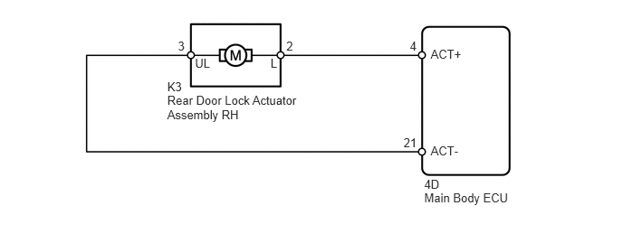
The slide door lock motor RH is built into the rear door lock actuator assembly RH.

The main body ECU controls the slide door lock motor RH to lock / unlock the slide door RH. This ECU applies current from the positive terminal to the negative terminal to operate the motor to lock the door. It reverses the direction of the current flow to operate the motor to unlock the door.

WIRING DIAGRAM
B138810E34
1.924,1.078 3.522,1.544 1.598,0.465 10 Rear Door Lock Actuator Assembly RH 2.243,0.646 2.469,0.822 0.225,0.177 10 UL 3.112,0.646 3.289,0.850 0.177,0.205 10 L 2.047,0.451 2.224,0.656 0.177,0.205 10 3 3.294,0.443 3.471,0.648 0.177,0.205 10 2 4.714,0.443 4.891,0.648 0.177,0.205 10 4 4.642,1.561 4.851,1.765 0.209,0.205 10 21 4.88,2.197 5.918,2.353 1.038,0.156 10 Main Body ECU 4.954,0.537 5.408,0.700 0.455,0.163 10 ACT+ 4.954,1.657 5.408,1.820 0.455,0.163 10 ACT- 4.88,2.042 5.133,2.205 0.253,0.163 10 4D 1.924,0.922 2.177,1.085 0.253,0.163 10 K3

PROCEDURE

1.PERFORM ACTIVE TEST USING INTELLIGENT TESTER (DOOR LOCK)
a.

Select the Active Test, use the intelligent tester to generate a control command, and then check that the doors lock / unlock.

Main body ECU
Item Test Details Diagnostic Note
DOOR LOCK Operate door lock motor
LOCK / UNLOCK
-

OK:

Doors can lock / unlock.


NG

2.INSPECT REAR DOOR LOCK ACTUATOR ASSEMBLY RH

OK

PROCEED TO NEXT CIRCUIT INSPECTION SHOWN IN PROBLEM SYMPTOMS TABLE

2.INSPECT REAR DOOR LOCK ACTUATOR ASSEMBLY RH
a.
B256272E06
0.285,0.427 0.727,0.609 0.442,0.181 10 Unlock 2.784,0.208 3.094,0.390 0.310,0.181 10 Lock 1.544,1.011 1.227,0.52 1.227,0.52 0.838,0.52 false 2.003,0.903 2.381,0.301 2.381,0.301 2.75,0.301 false 1.11,3.452 1.338,3.633 0.228,0.181 10 UL 2.219,3.452 2.343,3.619 0.123,0.167 10 L 1.623,4.177 1.222,3.632 false 1.861,4.177 2.262,3.633 false

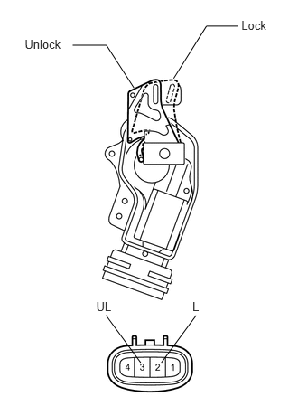
Remove the rear door lock actuator assembly RH.


b.

Apply battery voltage to the motor terminals and check the operation of the door lock motor.

OK:
Measurement Condition Result
Battery positive (+) → 2 (L)
Battery negative (-) → 3 (UL)
Locks
Battery positive (+) → 3 (UL)
Battery negative (-) → 2 (L)
Unlocks


OK

3.CHECK WIRE HARNESS (DOOR LCOK - ECU AND BODY GROUND)

NG

REPLACE REAR DOOR LOCK ACTUATOR ASSEMBLY RH

3.CHECK WIRE HARNESS (DOOR LCOK - ECU AND BODY GROUND)
a.
U188676E02
1.531,1.885 0.875,1.5 false 1.854,1.906 2.625,1.51 false 0.938,3.948 0.708,4.458 false 1.083,4.104 1.198,4.427 false 0.094,0.031 1.458,0.177 1.365,0.146 10 false Wire Harness Side: 0.26,0.729 2.719,0.875 2.458,0.146 10 false Rear Door Lock Actuator Assembly RH 0.49,1.802 0.76,1.958 0.271,0.156 10 false K3 1.156,3.052 2.26,3.219 1.104,0.167 10 false Main Body ECU 0.146,3.323 0.385,3.51 0.24,0.188 10 false 4D 0.76,1.354 0.917,1.521 0.156,0.167 10 false L 2.698,1.396 2.938,1.563 0.24,0.167 10 false UL 0.417,4.458 0.844,4.604 0.427,0.146 10 false ACT+ 1.115,4.438 1.542,4.583 0.427,0.146 10 false ACT-

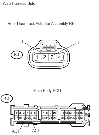
Disconnect the K3 rear door lock actuator assembly RH connector.


b.

Disconnect the 4D ECU connector.


c.

Measure the resistance of the wire harness side connectors.

Standard resistance:
Tester Connection Specified Condition
K3-2 (L) - 4D-4 (ACT+) Below 1 Ω
K3-3 (UL) - 4D-21 (ACT-) Below 1 Ω
K3-2 (L) - Body ground 10 kΩ or higher
K3-3 (UL) - Body ground 10 kΩ or higher


OK

PROCEED TO NEXT CIRCUIT INSPECTION SHOWN IN PROBLEM SYMPTOMS TABLE

NG

REPAIR OR REPLACE HARNESS OR CONNECTOR