RM24M0E
_58
Vehicle Interior
_059568
DOOR LOCK
_0292011
POWER DOOR LOCK CONTROL SYSTEM
J
DOOR LOCK POWER DOOR LOCK CONTROL SYSTEM Back Door Opener Switch Circuit
DESCRIPTION
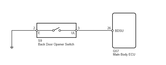
When the back door opener switch on the back door outside handle is pressed with all the doors unlocked, the main body ECU operates the back door lock motor to unlatch the back door.
WIRING DIAGRAM
1.644,1.828 3.280,1.992
1.636,0.164
10
Back Door Opener Switch
4.875,2.264 5.938,2.419
1.063,0.156
10
Main Body ECU
4.959,1.24 5.420,1.414
0.461,0.174
10
BDSU
4.875,2.117 5.225,2.291
0.350,0.174
10
G57
1.644,1.665 1.994,1.839
0.350,0.174
10
S9
1.64,1.332 1.815,1.543
0.174,0.211
10
E
3.074,1.332 3.291,1.478
0.216,0.147
10
UL
4.635,1.125 4.851,1.272
0.216,0.147
10
26
1.436,1.125 1.652,1.272
0.216,0.147
10
2
3.357,1.125 3.573,1.272
0.216,0.147
10
3
PROCEDURE
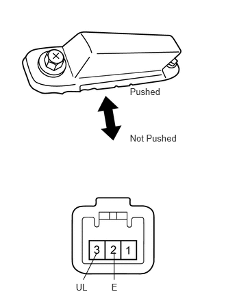
1.INSPECT BACK DOOR OPENER SWITCH
a.
1.975,1.313 2.562,1.502
0.586,0.188
10
Pushed
1.975,2.018 2.784,2.206
0.809,0.188
10
Not Pushed
1.694,4.29 1.878,4.459
0.184,0.170
10
E
1.153,4.29 1.378,4.473
0.225,0.184
10
UL
1.737,3.843 1.737,4.26
false
1.475,3.847 1.267,4.26
false
Remove the back door opener switch.
b.
Measure the resistance of the back door opener switch.
- Standard resistance:
Tester Connector Condition Specified Condition 2 (E) - 3 (UL) Not pushed 10 kΩ or higher 2 (E) - 3 (UL) Pushed Below 1 Ω
OK
2.CHECK WIRE HARNESS (SWITCH - ECU AND BODY GROUND)
NG
REPLACE BACK DOOR OUTSIDE HANDLE (BACK DOOR OPENER SWITCH)
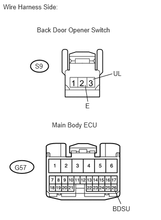
2.CHECK WIRE HARNESS (SWITCH - ECU AND BODY GROUND)
a.
0.068,0.059 1.488,0.255
1.420,0.196
10
Wire Harness Side:
0.788,0.551 2.514,0.700
1.725,0.149
10
Back Door Opener Switch
0.748,1.318 1.001,1.488
0.253,0.170
10
S9
1.109,2.573 2.171,2.736
1.062,0.163
10
Main Body ECU
0.311,3.477 0.633,3.647
0.323,0.170
10
G57
2.418,1.479 2.674,1.640
0.257,0.161
10
UL
1.822,2.167 1.964,2.329
0.142,0.162
10
E
2.403,4.358 2.844,4.500
0.441,0.142
10
BDSU
1.987,1.684 2.398,1.568
false
1.818,1.809 1.874,2.159
false
2.444,4.028 2.581,4.335
false
Disconnect the S9 back door opener switch connector.
b.
Disconnect the G57 ECU connector.
c.
Measure the resistance of the wire harness side connectors.
- Standard resistance:
Tester Connection Specified Condition S9-3 (UL) - G57-26 (BDSU) Below 1 Ω S9-2 (E) - Body ground Below 1 Ω S9-3 (UL) - Body ground 10 kΩ or higher
OK
PROCEED TO NEXT CIRCUIT INSPECTION SHOWN IN PROBLEM SYMPTOMS TABLE
NG
REPAIR OR REPLACE HARNESS OR CONNECTOR