ENGINE HOOD / DOOR POWER SLIDE DOOR SYSTEM TERMINALS OF ECU
CHECK MAIN BODY ECU
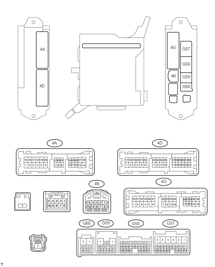
Disconnect the 4A, 4K and G59 ECU connectors.
Measure the voltage and resistance of the wire harness side connectors.
| Symbols (Terminal No.) | Wiring Color | Terminal Description | Condition | Specified Condition |
|---|---|---|---|---|
| BATB (4K-9) - Body ground | B - Body ground | Battery power supply | Always | 10 to 14 V |
| ACC (4A-26) - Body ground | GR - Body ground | ACC power supply | Engine switch on (ACC) | 10 to 14 V |
| ACC (4A-26) - Body ground | GR - Body ground | ACC power supply | Engine switch off | Below 1 V |
| GND2 (4A-3) - Body ground | W-B - Body ground | Ground | Always | Below 1 Ω |
| GND1 (G59-1) - Body ground | W-B - Body ground | Ground | Always | Below 1 Ω |
If the result is not as specified, there may be a malfunction in the wire harness.
Reconnect the 4A, 4K and G59 ECU connector.
Measure the voltage of the connectors.
| Symbols (Terminal No.) | Wiring Color | Terminal Description | Condition | Specified Condition |
|---|---|---|---|---|
| DCTY (G57-24) - Body ground | L - Body ground | Driver side door courtesy switch input | Driver side door closed | 10 to 14 V |
| DCTY (G57-24) - Body ground | L - Body ground | Driver side door courtesy switch input | Driver side door open | Below 1 V |
| PCTY (G58-21) - Body ground | L - Body ground | Front passenger side door courtesy switch input | Front passenger side door closed | 10 to 14 V |
| PCTY (G58-21) - Body ground | L - Body ground | Front passenger side door courtesy switch input | Front passenger side door open | Below 1 V |
| LCTY (4A-4) - Body ground | O - Body ground | Slide door LH courtesy light switch input | Slide door LH closed | 10 to 14 V |
| LCTY (4A-4) - Body ground | O - Body ground | Slide door LH courtesy light switch input | Slide door LH open | Below 1 V |
| RCTY (G58-7) - Body ground | LG - Body ground | Slide door RH courtesy light switch input | Slide door RH closed | 10 to 14 V |
| RCTY (G58-7) - Body ground | LG - Body ground | Slide door RH courtesy light switch input | Slide door RH open | Below 1 V |
| BCTY (G58-25) - Body ground | W - Body ground | Back door courtesy light switch input | Back door closed | 10 to 14 V |
| BCTY (G58-25) - Body ground | W - Body ground | Back door courtesy light switch input | Back door open | Below 1 V |
| ACT+ (4D-5) - Body ground*1 | SB - Body ground | Driver side door lock motor LOCK drive output | Master switch (door control switch) or driver side door key cylinder LOCK | 10 to 14 V |
| ACT+ (4D-5) - Body ground*1 | SB - Body ground | Driver side door lock motor LOCK drive output | Master switch (door control switch) or driver side door key cylinder OFF | Below 1 V |
| ACT+ (4D-1) - Body ground*2 | R - Body ground | Driver side door lock motor LOCK drive output | Master switch (door control switch) or driver side door key cylinder LOCK | 10 to 14 V |
| ACT+ (4D-1) - Body ground*2 | R - Body ground | Driver side door lock motor LOCK drive output | Master switch (door control switch) or driver side door key cylinder OFF | Below 1 V |
| ACT- (4D-21) - Body ground*1 | W - Body ground | Driver side door lock motor UNLOCK drive output | Master switch (door control switch) or driver side door key cylinder UNLOCK | 10 to 14 V |
| ACT- (4D-21) - Body ground*1 | W - Body ground | Driver side door lock motor UNLOCK drive output | Master switch (door control switch) or driver side door key cylinder OFF | Below 1 V |
| ACT- (4D-20) - Body ground*2 | O - Body ground | Driver side door lock motor UNLOCK drive output | Master switch (door control switch) or driver side door key cylinder UNLOCK | 10 to 14 V |
| ACT- (4D-20) - Body ground*2 | O - Body ground | Driver side door lock motor UNLOCK drive output | Master switch (door control switch) or driver side door key cylinder OFF | Below 1 V |
| ACT+ (4D-1) - Body ground*1 | R - Body ground | Front passenger side door lock motor LOCK drive output | Master switch (door control switch) or driver side door key cylinder LOCK | 10 to 14 V |
| ACT+ (4D-1) - Body ground*1 | R - Body ground | Front passenger side door lock motor LOCK drive output | Master switch (door control switch) or driver side door key cylinder OFF | Below 1 V |
| ACT+ (4D-5) - Body ground*2 | SB - Body ground | Front passenger side door lock motor LOCK drive output | Master switch (door control switch) or driver side door key cylinder LOCK | 10 to 14 V |
| ACT+ (4D-5) - Body ground*2 | SB - Body ground | Front passenger side door lock motor LOCK drive output | Master switch (door control switch) or driver side door key cylinder OFF | Below 1 V |
| ACT- (4D-20) - Body ground*1 | O - Body ground | Front passenger side door lock motor UNLOCK drive output | Master switch (door control switch) or driver side door key cylinder UNLOCK | 10 to 14 V |
| ACT- (4D-20) - Body ground*1 | O - Body ground | Front passenger side door lock motor UNLOCK drive output | Master switch (door control switch) or driver side door key cylinder OFF | Below 1 V |
| ACT- (4D-21) - Body ground*2 | W - Body ground | Front passenger side door lock motor UNLOCK drive output | Master switch (door control switch) or driver side door key cylinder UNLOCK | 10 to 14 V |
| ACT- (4D-21) - Body ground*2 | W - Body ground | Front passenger side door lock motor UNLOCK drive output | Master switch (door control switch) or driver side door key cylinder OFF | Below 1 V |
| ACT+ (4G-7) - Body ground | Y - Body ground | Slide door LH lock motor LOCK drive output | Master switch (door control switch) or driver side door key cylinder LOCK | 10 to 14 V |
| ACT+ (4G-7) - Body ground | Y - Body ground | Slide door LH lock motor LOCK drive output | Master switch (door control switch) or driver side door key cylinder OFF | Below 1 V |
| ACT- (4G-23) - Body ground | L - Body ground | Slide door LH lock motor UNLOCK drive output | Master switch (door control switch) or driver side door key cylinder UNLOCK | 10 to 14 V |
| ACT- (4G-23) - Body ground | L - Body ground | Slide door LH lock motor UNLOCK drive output | Master switch (door control switch) or driver side door key cylinder OFF | Below 1 V |
| ACT+ (4D-4) - Body ground | GR - Body ground | Slide door RH lock motor LOCK drive output | Master switch (door control switch) or driver side door key cylinder LOCK | 10 to 14 V |
| ACT+ (4D-4) - Body ground | GR - Body ground | Slide door RH lock motor LOCK drive output | Master switch (door control switch) or driver side door key cylinder OFF | Below 1 V |
| ACT- (4D-21) - Body ground | W - Body ground | Slide door RH lock motor UNLOCK drive output | Master switch (door control switch) or driver side door key cylinder UNLOCK | 10 to 14 V |
| ACT- (4D-21) - Body ground | W - Body ground | Slide door RH lock motor UNLOCK drive output | Master switch (door control switch) or driver side door key cylinder OFF | Below 1 V |
| LSWD (G57-9) - Body ground | SB - Body ground | Driver side door lock position switch input | Driver side door LOCK | 10 to 14 V |
| LSWD (G57-9) - Body ground | SB - Body ground | Driver side door lock position switch input | Driver side door UNLOCK | Below 1 V |
| LSWL (4D-6) - Body ground | SB - Body ground | Slide door LH lock position switch input | Slide door LH LOCK | Pulse generation |
| LSWL (4D-6) - Body ground | SB - Body ground | Slide door LH lock position switch input | Slide door LH UNLOCK | Below 1 V |
| LSWR (G58-5) - Body ground | Y - Body ground | Slide door RH lock position switch input | Slide door RH LOCK | 10 to 14 V |
| LSWR (G58-5) - Body ground | Y - Body ground | Slide door RH lock position switch input | Slide door RH UNLOCK | Below 1 V |
- HINT:
-
*1: for LHD
-
*2: for RHD
If the result is not as specified, the ECU may have a malfunction.
CHECK DOOR CONTROL RELAY LH (POWER SLIDE DOOR ECU LH)

Disconnect the L6 and M22 ECU connectors.
Measure the voltage and resistance of each terminal of the wire harness side connectors.
| Symbols (Terminal No.) | Wiring Color | Terminal Description | Condition | Specified Condition |
|---|---|---|---|---|
| B (M22-7) - GND (M22-1) | R - W-B | Power supply | Always | 10 to 14 V |
| ECUB (M22-12) - GND (M22-1) | R - W-B | Power supply | Always | 10 to 14 V |
| IG (M22-4) - GND (M22-1) | R - W-B | Power supply | Engine switch on (IG) | 10 to 14 V |
| GND (M22-1) - Body ground | W-B - Body ground | Ground | Always | Below 1 Ω |
| MSW (M22-8) - GND (M22-1) | B - W-B | Main switch input | Power slide door main switch OFF and Fuel lid is closed | Below 1 Ω |
| Power slide door main switch ON and Fuel lid is open | 10 kΩ or higher | |||
| POL (L6-2) - GND (M22-1) | G - W-B | PAWL switch input | Slide door fully closed to open | 10 kΩ or higher → Below 1 Ω → 10 kΩ or higher |
| Partially closed door | Below 1 Ω | |||
| Slide door fully opened to close | 10 kΩ or higher → Below 1 Ω → 10 kΩ or higher | |||
| FUL (L6-5) - GND (M22-1) | BR - W-B | Full-latch switch | Slide door open to fully closed | Below 1 Ω → 10 kΩ or higher |
| HAF (L6-12) - GND (M22-1) | V - W-B | Half-latch switch input | Slide door fully open → partially closed | Below 1 Ω → 10 kΩ or higher |
| DS2 (L6-7) - GND (M22-1) | Y - W-B | Handle switch | Handle not operated | 10 kΩ or higher |
| Pull the outside handle or Turn the inside handle to close | Below 1 Ω | |||
| DS1 (L6-10) - GND (M22-1) | L - W-B | Handle switch | Handle not operated | 10 kΩ or higher |
| Pull the outside handle or Turn the inside handle to open | Below 1 Ω | |||
| OS (L6-8) - OSG (L6-4) | GR - W | Touch switch input | Power slide door sensor pushed | Below 100 Ω |
| Power slide door sensor is not pushed | Between 500 Ω and 1100 Ω |
Reconnect the M22 ECU connectors.
Measure the voltage of the connectors.
| Symbols (Terminal No.) | Wiring Color | Terminal Description | Condition | Specified Condition |
|---|---|---|---|---|
| DC- (L6-1) - GND (M22-1) | G - W-B | Door closer output (Reverse rotation) | Slide door open | Below 1 V |
| Partially closed door | Below 1 V | |||
| Normal rotation | Below 1 V | |||
| Reverse rotation | 10 to 14 V | |||
| Operation finished | Below 1 V | |||
| DC+ (L6-9) - GND (M22-1) | L - W-B | Door closer output (Normal rotation) | Slide door open | Below 1 V |
| Partially closed door | Below 1 V | |||
| Normal rotation | 10 to 14 V | |||
| Reverse rotation | Below 1 V | |||
| Operation finished | Below 1 V | |||
| LMT (L6-11) - GND (M22-1) | B - W-B | Initial position switch input | Slide door open | Below 1 V |
| Partially closed door | Below 1 V | |||
| Normal rotation | Below 1 V | |||
| Reverse rotation | Below 1 V | |||
| Operation finished | 10 to 14 V | |||
| RACT (L6-13) - GND (M22-1) | R - W-B | Latch release output | Slide door fully closed and power slide door control switch OFF to ON or Power slide door control switch ON (Wireless operation) | Below 1 V |
| Operating slide door close | Below 1 V | |||
| Partially closed door | 10 to 14 V | |||
| Slide door fully open | Below 1 V |
CHECK DOOR CONTROL RELAY RH (POWER SLIDE DOOR ECU RH)

Disconnect the K6 and N24 ECU connectors.
Measure the voltage and resistance of each terminal of the wire harness side connectors.
| Symbols (Terminal No.) | Wiring Color | Terminal Description | Condition | Specified Condition |
|---|---|---|---|---|
| B (N24-12) - GND (N24-6) | R - W-B | Power supply | Always | 10 to 14 V |
| ECUB (N24-7) - GND (N24-6) | LG - W-B | Power supply | Always | 10 to 14 V |
| IG (N24-3) - GND (N24-6) | R - W-B | Power supply | Engine switch on (IG) | 10 to 14 V |
| GND (N24-6) - Body ground | W-B - Body ground | Ground | Always | Below 1 Ω |
| MSW (N24-11) - GND (N24-6) | LG - W-B | Main switch input | Power slide door main switch OFF and Fuel lid is closed | Below 1 Ω |
| Power slide door main switch ON and Fuel lid is open | 10 kΩ or higher | |||
| POL (K6-4) - GND (N24-6) | G - W-B | PAWL switch input | Slide door fully closed to open | 10 kΩ or higher → Below 1 Ω → 10 kΩ or higher |
| Partially closed door | Below 1 Ω | |||
| Slide door fully opened to close | 10 kΩ or higher → Below 1 Ω → 10 kΩ or higher | |||
| FUL (K6-1) - GND (N24-6) | BR - W-B | Full-latch switch | Slide door open to fully closed | Below 1 Ω → 10 kΩ or higher |
| HAF (K6-10) - GND (N24-6) | V - W-B | Half-latch switch input | Slide door fully open → partially closed | Below 1 Ω → 10 kΩ or higher |
| DS2 (K6-7) - GND (N24-6) | Y - W-B | Handle switch | Handle not operated | 10 kΩ or higher |
| Pull the outside handle or Turn the inside handle to close | Below 1 Ω | |||
| DS1 (K6-12) - GND (N24-6) | V - W-B | Handle switch | Handle not operated | 10 kΩ or higher |
| Pull the outside handle or Turn the inside handle to open | Below 1 Ω | |||
| OS (K6-6) - OSG (K6-2) | GR - W | Touch switch input | Power slide door sensor pushed | Below 100 Ω |
| Power slide door sensor is not pushed | Below 1 Ω |
Reconnect the K6 and N24 ECU connectors.
Measure the voltage of the connectors.
| Symbols (Terminal No.) | Wiring Color | Terminal Description | Condition | Specified Condition |
|---|---|---|---|---|
| DC- (K6-5) - GND (N24-6) | G - W-B | Door closer output (Reverse rotation) | Slide door open | Below 1 V |
| Partially closed door | Below 1 V | |||
| Normal rotation | Below 1 V | |||
| Reverse rotation | 10 to 14 V | |||
| Operation finished | Below 1 V | |||
| DC+ (K6-13) - GND (N24-6) | L - W-B | Door closer output (Normal rotation) | Slide door open | Below 1 V |
| Partially closed door | Below 1 V | |||
| Normal rotation | Below 1 V | |||
| Reverse rotation | 10 to 14 V | |||
| Operation finished | Below 1 V | |||
| LMT (K6-11) - GND (N24-6) | B - W-B | Initial position switch input | Slide door open | Below 1 V |
| Partially closed door | Below 1 V | |||
| Normal rotation | Below 1 V | |||
| Reverse rotation | 10 to 14 V | |||
| Operation finished | Below 1 V | |||
| RACT (K6-9) - GND (N24-6) | R - W-B | Latch release output | Slide door fully closed and power slide door control switch OFF to ON or Power slide door control switch ON (Wireless operation) | Below 1 V |
| Operating slide door close | Below 1 V | |||
| Partially closed door | 10 to 14 V | |||
| Slide door fully open | Below 1 V |