RM24M0E
_58
Vehicle Interior
_059569
ENGINE HOOD / DOOR
_0292019
POWER SLIDE DOOR SYSTEM
J
ENGINE HOOD / DOOR POWER SLIDE DOOR SYSTEM Slide Door Lock Release Motor RH Circuit
DESCRIPTION
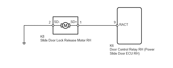
The slide door lock release motor unlocks the power slide door lock and unlock position switch when the power slide door is operated by the transmitter or power slide door control switch with the slide door closed.
WIRING DIAGRAM
1.67,1.577 3.889,1.733
2.218,0.156
10
Slide Door Lock Release Motor RH
2.92,0.817 3.249,0.976
0.328,0.159
10
SD+
4.547,1.795 4.876,1.955
0.328,0.159
10
K6
1.67,1.419 1.894,1.579
0.224,0.159
10
K8
2.236,0.817 2.559,0.976
0.323,0.159
10
SD-
2.019,0.833 2.175,0.992
0.156,0.159
10
2
3.303,0.833 3.459,0.992
0.156,0.159
10
1
4.714,0.833 4.877,0.992
0.163,0.159
10
9
4.94,0.924 5.364,1.093
0.424,0.168
10
RACT
4.547,1.95 6.388,2.299
1.841,0.349
10
Door Control Relay RH (Power Slide Door ECU RH)
PROCEDURE
1.INSPECT SLIDE DOOR LOCK RELEASE MOTOR RH
a.
2.095,2.228 3.191,2.416
1.096,0.188
10
26.0 to 30.3 mm
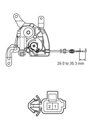
Remove the slide door lock release motor.
b.
Apply the battery voltage to the motor terminals and check the operation of the door lock release motor.
- OK:
Measurement Condition Specified Condition Battery positive (+) → 1 (SD+)
Battery negative (-) → 2 (SD-)Lock release
- Standard stroke:
26.0 to 30.3 mm (1.02 to 1.19 in.)
OK
2.CHECK WIRE HARNESS (RELEASE MOTOR - ECU AND BODY GROUND)
NG
REPLACE SLIDE DOOR LOCK RELEASE MOTOR RH
2.CHECK WIRE HARNESS (RELEASE MOTOR - ECU AND BODY GROUND)
a.
2.219,3.458 2.073,4.208
false
1.875,1.792 2.302,1.583
false
1.135,2.063 1.563,1.854
false
0.135,0.115 1.531,0.281
1.396,0.167
10
false
Wire Harness Side:
0.667,0.802 2.875,0.958
2.208,0.156
10
false
Slide Door Lock Release Motor RH
1,2.615 2.479,2.771
1.479,0.156
10
false
Door Control Relay RH
0.781,1.344 0.979,1.531
0.198,0.188
10
false
K8
0.563,3.229 0.854,3.417
0.292,0.188
10
false
K6
0.906,2.083 1.229,2.24
0.323,0.156
10
false
SD-
2.333,1.51 2.656,1.667
0.323,0.156
10
false
SD+
1.917,4.25 2.313,4.406
0.396,0.156
10
false
RACT
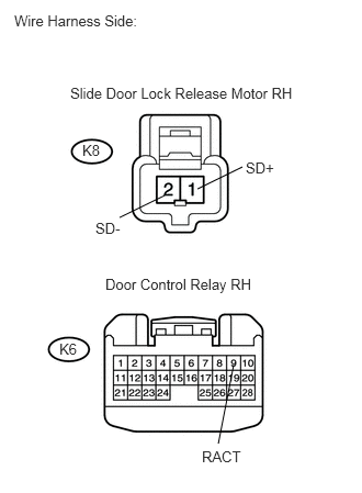
Disconnect the K8 release motor connector.
b.
Disconnect the K6 ECU connector.
c.
Measure the resistance of the wire harness side connectors.
- Standard resistance:
Tester Connection Specified Condition K8-1 (SD+) - K6-9 (RACT) Below 1 Ω K8-2 (SD-) - Body ground Below 1 Ω K8-1 (SD+) - Body ground 10 kΩ or higher
OK
PROCEED TO NEXT CIRCUIT INSPECTION SHOWN IN PROBLEM SYMPTOMS TABLE
NG
REPAIR OR REPLACE HARNESS OR CONNECTOR