ENGINE HOOD / DOOR SLIDE DOOR CLOSER SYSTEM TERMINALS OF ECU
CHECK DOOR CONTROL RELAY LH (POWER SLIDE DOOR ECU LH) (w/ Power Slide Door LH)
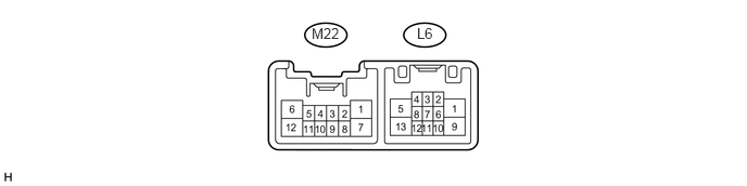
Disconnect the L6 and M22 ECU connectors.
Measure the voltage and resistance of each terminal of the wire harness side connectors.
| Symbols (Terminal No.) | Wiring Color | Terminal Description | Condition | Specified Condition |
|---|---|---|---|---|
| B (M22-7) - GND (M22-1) | R - W-B | Power supply | Always | 10 to 14 V |
| ECUB (M22-12) - GND (M22-1) | R - W-B | Power supply | Always | 10 to 14 V |
| IG (M22-4) - GND (M22-1) | R - W-B | Power supply | Ignition switch ON | 10 to 14 V |
| GND (M22-1) - Body ground | W-B - Body ground | Ground | Always | Below 1 Ω |
| MSW (M22-8) - GND (M22-1) | B - W-B | Main switch input | Power slide door main switch OFF and fuel lid closed | Below 1 Ω |
| Power slide door main switch ON or fuel lid open | 10 kΩ or higher | |||
| POL (L6-2) - GND (M22-1) | G - W-B | PAWL switch input | Slide door fully closed to open | 10 kΩ or higher → Below 1 Ω → 10 kΩ or higher |
| Partially closed door | Below 1 Ω | |||
| Slide door fully opened to close | 10 kΩ or higher → Below 1 Ω → 10 kΩ or higher | |||
| FUL (L6-5) - GND (M22-1) | BR - W-B | Full-latch switch input | Slide door open to fully closed | Below 1 Ω → 10 kΩ or higher |
| HAF (L6-12) - GND (M22-1) | O - W-B | Half-latch switch input | Slide door fully open → partially closed | Below 1 Ω → 10 kΩ or higher |
| DS2 (L6-7) - GND (M22-1) | LG - W-B | Handle switch | Handle not operated | 10 kΩ or higher |
| Pull the outside handle or turn the inside handle to close | Below 1 Ω | |||
| DS1 (L6-10) - GND (M22-1) | V - W-B | Handle switch | Handle not operated | 10 kΩ or higher |
| Pull the outside handle or turn the inside handle to open | Below 1 Ω | |||
| OS (L6-8) - OSG (L6-4) | GR - W | Touch switch input | Power slide door sensor pushed | Below 100 Ω |
| Power slide door sensor not pushed | Between 500 Ω and 1100 Ω |
Reconnect the L6 and M22 ECU connectors.
Measure the voltage of the connectors.
| Symbols (Terminal No.) | Wiring Color | Terminal Description | Condition | Specified Condition |
|---|---|---|---|---|
| DC- (L6-1) - GND (M22-1) | G - W-B | Door closer output (Reverse rotation) | Slide door open | Below 1 V |
| Partially closed door | Below 1 V | |||
| Normal rotation | Below 1 V | |||
| Reverse rotation | 10 to 14 V | |||
| Operation finished | Below 1 V | |||
| DC+ (L6-9) - GND (M22-1) | L - W-B | Door closer output (Normal rotation) | Slide door open | Below 1 V |
| Partially closed door | Below 1 V | |||
| Normal rotation | 10 to 14 V | |||
| Reverse rotation | Below 1 V | |||
| Operation finished | Below 1 V | |||
| LMT (L6-11) - GND (M22-1) | B - W-B | Initial position switch input | Slide door open | Below 1 V |
| Partially closed door | Below 1 V | |||
| Normal rotation | Below 1 V | |||
| Reverse rotation | Below 1 V | |||
| Operation finished | 10 to 14 V | |||
| RACT (L6-13) - GND (M22-1) | R - W-B | Latch release output | Slide door fully closed and power slide door control switch OFF to ON or power slide door control switch ON (Wireless operation) | Below 1 V |
| Operating slide door close | Below 1 V | |||
| Partially closed door | 10 to 14 V | |||
| Slide door fully open | Below 1 V |
CHECK SLIDE DOOR CLOSER RELAY LH (w/o Power Slide Door LH)

Disconnect the L12 relay connector.
Measure the voltage and resistance of each terminal of the wire harness side connectors.
| Symbols (Terminal No.) | Wiring Color | Terminal Description | Condition | Specified Condition |
|---|---|---|---|---|
| +B (L12-5) - E (L12-8) | R - W-B | Power supply | Always | 10 to 14 V |
| E (L12-8) - Body ground | W-B - Body ground | Ground | Always | Below 1 Ω |
| FULL (L12-3) - GND (L12-7) | BR - W-B | Full-latch switch input | Slide door open to fully closed | Below 1 Ω → 10 kΩ or higher |
| HALF (L12-4) - GND (L12-7) | V - W-B | Half-latch switch input | Slide door fully open → partially closed | Below 1 Ω → 10 kΩ or higher |
| A+ (L12-9) - GND (L12-7) | G - W-B | Pawl switch input | Slide door fully closed to open | 10 kΩ or higher → Below 1 Ω → 10 kΩ or higher |
| A+ (L12-9) - GND (L12-7) | G - W-B | Pawl switch input | Partially closed door | Below 1 Ω |
| A+ (L12-9) - GND (L12-7) | G - W-B | Pawl switch input | Slide door fully opened to close | 10 kΩ or higher → Below 1 Ω → 10 kΩ or higher |
Reconnect the L12 relay connector.
Measure the voltage of the connectors.
| Symbols (Terminal No.) | Wiring Color | Terminal Description | Condition | Specified Condition |
|---|---|---|---|---|
| ACT- (L12-1) - GND (L12-7) | G - W-B | Door closer output (Reverse rotation) | Slide door open | Below 1 V |
| Partially closed door | Below 1 V | |||
| Normal rotation | Below 1 V | |||
| Reverse rotation | 10 to 14 V | |||
| Operation finished | Below 1 V | |||
| ACT+ (L12-2) - GND (L12-7) | L - W-B | Door closer output (Normal rotation) | Slide door open | Below 1 V |
| Partially closed door | Below 1 V | |||
| Normal rotation | 10 to 14 V | |||
| Reverse rotation | Below 1 V | |||
| Operation finished | Below 1 V | |||
| LSW (L12-10) - GND (L12-7) | W-B - W-B | Initial position switch input | Slide door open | 10 to 14 V |
| Partially closed door | 10 to 14 V | |||
| Normal rotation | Below 1 V | |||
| Pull the outside handle or inside handle | 10 to 14 V | |||
| Reverse rotation | Below 1 V | |||
| Operation finished | 10 to 14 V |
CHECK DOOR CONTROL RELAY RH (POWER SLIDE DOOR ECU RH) (w/ Power Slide Door RH)
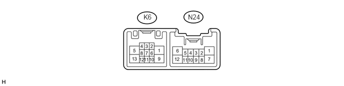
Disconnect the K6 and N24 ECU connectors.
Measure the voltage and resistance of each terminal of the wire harness side connectors.
| Symbols (Terminal No.) | Wiring Color | Terminal Description | Condition | Specified Condition |
|---|---|---|---|---|
| B (N24-12) - GND (N24-6) | R - W-B | Power supply | Always | 10 to 14 V |
| ECUB (N24-7) - GND (N24-6) | LG - W-B | Power supply | Always | 10 to 14 V |
| IG (N24-3) - GND (N24-6) | R - W-B | Power supply | Ignition switch ON | 10 to 14 V |
| GND (N24-6) - Body ground | W-B - Body ground | Ground | Always | Below 1 Ω |
| MSW (N24-11) - GND (N24-6) | LG - W-B | Main switch input | Power slide door main switch OFF | Below 1 Ω |
| Power slide door main switch ON | 10 kΩ or higher | |||
| POL (K6-4) - GND (N24-6) | G - W-B | PAWL switch input | Slide door fully closed to open | 10 kΩ or higher → Below 1 Ω → 10 kΩ or higher |
| Partially closed door | Below 1 Ω | |||
| Slide door fully opened to close | 10 kΩ or higher → Below 1 Ω → 10 kΩ or higher | |||
| FUL (K6-1) - GND (N24-6) | BR - W-B | Full-latch switch input | Slide door open to fully closed | Below 1 Ω → 10 kΩ or higher |
| HAF (K6-10) - GND (N24-6) | O - W-B | Half-latch switch input | Slide door fully open → partially closed | Below 1 Ω → 10 kΩ or higher |
| DS2 (K6-7) - GND (N24-6) | LG - W-B | Handle switch | Handle not operated | 10 kΩ or higher |
| Pull the outside handle or turn the inside handle to close | Below 1 Ω | |||
| DS1 (K6-12) - GND (N24-6) | V - W-B | Handle switch | Handle not operated | 10 kΩ or higher |
| Pull the outside handle or turn the inside handle to open | Below 1 Ω | |||
| OS (K6-6) - OSG (K6-2) | GR - W | Touch switch input | Power slide door sensor pushed | Below 100 Ω |
| Power slide door sensor not pushed | Between 500 Ω and 1100 Ω |
Reconnect the K6 and N24 ECU connectors.
Measure the voltage of the connectors.
| Symbols (Terminal No.) | Wiring Color | Terminal Description | Condition | Specified Condition |
|---|---|---|---|---|
| DC- (K6-5) - GND (N24-6) | G - W-B | Door closer output (Reverse rotation) | Slide door open | Below 1 V |
| Partially closed door | Below 1 V | |||
| Normal rotation | Below 1 V | |||
| Reverse rotation | 10 to 14 V | |||
| Operation finished | Below 1 V | |||
| DC+ (K6-13) - GND (N24-6) | L - W-B | Door closer output (Normal rotation) | Slide door open | Below 1 V |
| Partially closed door | Below 1 V | |||
| Normal rotation | 10 to 14 V | |||
| Reverse rotation | Below 1 V | |||
| Operation finished | Below 1 V | |||
| LMT (K6-11) - GND (N24-6) | B - W-B | Initial position switch input | Slide door open | Below 1 V |
| Partially closed door | Below 1 V | |||
| Normal rotation | Below 1 V | |||
| Reverse rotation | Below 1 V | |||
| Operation finished | 10 to 14 V | |||
| RACT (K6-9) - GND (N24-6) | R - W-B | Latch release output | Slide door fully closed and power slide door control switch OFF to ON or power slide door control switch ON (Wireless operation) | Below 1 V |
| Operating slide door close | Below 1 V | |||
| Partially closed door | 10 to 14 V | |||
| Slide door fully open | Below 1 V |
CHECK SLIDE DOOR CLOSER RELAY RH (w/o Power Slide Door RH)

Disconnect the K12 relay connector.
Measure the voltage and resistance of each terminal of the wire harness side connectors.
| Symbols (Terminal No.) | Wiring Color | Terminal Description | Condition | Specified Condition |
|---|---|---|---|---|
| +B (K12-5) - E (K12-8) | R - W-B | Power supply | Always | 10 to 14 V |
| E (K12-8) - Body ground | W-B - Body ground | Ground | Always | Below 1 Ω |
| FULL (K12-3) - GND (K12-7) | BR - W-B | Full-latch switch input | Slide door open to fully closed | Below 1 Ω → 10 kΩ or higher |
| HALF (K12-4) - GND (K12-7) | V - W-B | Half-latch switch input | Slide door fully open → partially closed | Below 1 Ω → 10 kΩ or higher |
| A+ (K12-9) - GND (K12-7) | G - W-B | Pawl switch input | Slide door fully closed to open | 10 kΩ or higher → Below 1 Ω → 10 kΩ or higher |
| A+ (K12-9) - GND (K12-7) | G - W-B | Pawl switch input | Partially closed door | Below 1 Ω |
| A+ (K12-9) - GND (K12-7) | G - W-B | Pawl switch input | Slide door fully opened to close | 10 kΩ or higher → Below 1 Ω → 10 kΩ or higher |
Reconnect the K12 relay connector.
Measure the voltage of the connectors.
| Symbols (Terminal No.) | Wiring Color | Terminal Description | Condition | Specified Condition |
|---|---|---|---|---|
| ACT- (K12-1) - GND (K12-7) | G - W-B | Door closer output (Reverse rotation) | Slide door open | Below 1 V |
| Partially closed door | Below 1 V | |||
| Normal rotation | Below 1 V | |||
| Reverse rotation | 10 to 14 V | |||
| Operation finished | Below 1 V | |||
| ACT+ (K12-2) - GND (K12-7) | L - W-B | Door closer output (Normal rotation) | Slide door open | Below 1 V |
| Partially closed door | Below 1 V | |||
| Normal rotation | 10 to 14 V | |||
| Reverse rotation | Below 1 V | |||
| Operation finished | Below 1 V | |||
| LSW (K12-10) - GND (K12-7) | B - W-B | Initial position switch input | Slide door open | 10 to 14 V |
| Partially closed door | 10 to 14 V | |||
| Normal rotation | Below 1 V | |||
| Pull the outside handle or inside handle | 10 to 14 V | |||
| Reverse rotation | Below 1 V | |||
| Operation finished | 10 to 14 V |