RM24M0E
_58
Vehicle Interior
_059569
ENGINE HOOD / DOOR
_0292020
SLIDE DOOR CLOSER SYSTEM
J
ENGINE HOOD / DOOR SLIDE DOOR CLOSER SYSTEM Slide Door Closer Motor LH Circuit
DESCRIPTION
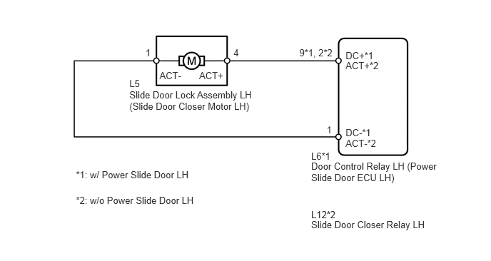
The power slide door ECU*1 or slide door closer relay*2 controls the slide door lock motor. This ECU*1 or relay*2 applies current to terminals DC+ and DC- to operate the motor to close the door. It reverses the direction of the current to operate the motor to open the door.
*1: w/ Power Slide Door LH
*2: w/o Power Slide Door LH
WIRING DIAGRAM
1.889,1.304 3.777,1.627
1.887,0.323
10
Slide Door Lock Assembly LH (Slide Door Closer Motor LH)
1.889,1.131 2.073,1.278
0.184,0.147
10
L5
2.907,1.024 3.304,1.208
0.397,0.184
10
ACT+
2.328,1.024 2.725,1.208
0.397,0.184
10
ACT-
3.407,0.688 3.535,0.834
0.128,0.147
10
4
4.369,0.688 4.886,0.834
0.517,0.147
10
9*1, 2*2
4.766,1.813 4.890,1.960
0.123,0.147
10
1
2.123,0.688 2.251,0.834
0.128,0.147
10
1
5.044,0.732 5.505,0.879
0.461,0.147
10
DC+*1
5.044,0.877 5.563,1.023
0.519,0.147
10
ACT+*2
5.044,2.007 5.563,2.154
0.519,0.147
10
ACT-*2
5.044,1.858 5.478,2.004
0.434,0.147
10
DC-*1
4.542,2.346 6.466,2.677
1.924,0.332
10
Door Control Relay LH (Power Slide Door ECU LH)
4.542,3.2 6.286,3.351
1.744,0.151
10
Slide Door Closer Relay LH
4.542,2.199 4.851,2.345
0.309,0.147
10
L6*1
4.542,3.048 4.927,3.195
0.385,0.147
10
L12*2
1.109,2.467 2.839,2.623
1.730,0.156
10
*1: w/ Power Slide Door LH
1.109,2.845 2.913,3.001
1.804,0.156
10
*2: w/o Power Slide Door LH
PROCEDURE
1.INSPECT SLIDE DOOR LOCK ASSEMBLY LH
a.
0.198,0.26 1.302,0.604
1.104,0.344
10
false
Normal Rotation (Close)
1.677,2.604 2.854,2.99
1.177,0.385
10
false
Reverse Rotation (Return)
Remove the slide door lock assembly LH.
b.
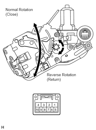
Apply battery voltage to the motor terminals and check the operation of the door lock motor.
- OK:
Tester Connection Specified Condition Battery positive (+) → 4 (ACT+)
Battery negative (-) → 1 (ACT-)Close operation Battery positive (+) → 1 (ACT-)
Battery negative (-) → 4 (ACT+)Return operation
OK
2.CHECK WIRE HARNESS (CLOSER MOTOR - ECU AND BODY GROUND)
NG
REPLACE SLIDE DOOR LOCK ASSEMBLY LH
2.CHECK WIRE HARNESS (CLOSER MOTOR - ECU AND BODY GROUND)
a.
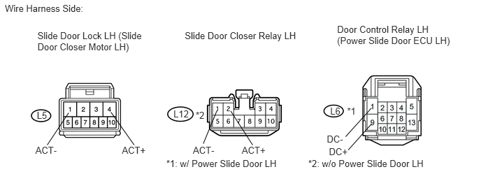
Disconnect L5 closer motor connector.
0.073,0.038 1.372,0.218
1.299,0.179
10
Wire Harness Side:
0.558,0.445 2.186,0.777
1.628,0.332
10
Slide Door Lock LH (Slide Door Closer Motor LH)
2.753,0.445 4.520,0.601
1.767,0.156
10
Slide Door Closer Relay LH
5.023,0.353 6.790,0.691
1.767,0.338
10
Door Control Relay LH (Power Slide Door ECU LH)
0.549,1.64 0.760,1.787
0.211,0.147
10
L5
2.585,1.617 2.850,1.764
0.265,0.147
10
L12
4.92,1.57 5.132,1.717
0.211,0.147
10
L6
0.528,2.154 0.913,2.303
0.385,0.149
10
ACT-
2.875,2.154 3.251,2.303
0.376,0.149
10
ACT-
4.869,1.991 5.164,2.140
0.295,0.149
10
DC-
3.603,2.154 3.983,2.303
0.380,0.149
10
ACT+
4.901,2.177 5.238,2.326
0.336,0.149
10
DC+
1.817,2.154 2.202,2.303
0.385,0.149
10
ACT+
1.022,1.682 0.703,2.161
false
1.653,1.672 1.999,2.161
false
3.233,1.646 3.029,2.14
false
3.437,1.654 3.764,2.161
false
5.534,1.61 5.149,2.037
false
5.534,1.848 5.188,2.235
false
2.917,1.631 3.077,1.778
0.161,0.147
10
*2
5.172,1.575 5.333,1.722
0.161,0.147
10
*1
2.478,2.355 4.245,2.511
1.767,0.156
10
*1: w/ Power Slide Door LH
4.593,2.355 6.397,2.511
1.804,0.156
10
*2: w/o Power Slide Door LH
b.
Disconnect L6*1 or L12*2 connector.
*1: w/ Power Slide Door LH
*2: w/o Power Slide Door LH
c.
Measure the resistance of the wire harness side connectors.
- Standard resistance:
Tester Connection Specified Condition L5-1 (ACT-) - L6-1 (DC-)*1 Below 1Ω L5-4 (ACT+) - L6-9 (DC+)*1 Below 1Ω L5-1 (ACT-) - L12-1 (ACT-)*2 Below 1Ω L5-4 (ACT+) - L12-2 (ACT+)*2 Below 1Ω L5-1 (ACT-) - Body ground 10 kΩ or higher L5-4 (ACT+) - Body ground 10 kΩ or higher
*1: w/ Power Slide Door LH
*2: w/o Power Slide Door LH
OK
PROCEED TO NEXT CIRCUIT INSPECTION SHOWN IN PROBLEM SYMPTOMS TABLE
NG
REPAIR OR REPLACE HARNESS OR CONNECTOR