RM24M0E
_58
Vehicle Interior
_059569
ENGINE HOOD / DOOR
_0292020
SLIDE DOOR CLOSER SYSTEM
J
ENGINE HOOD / DOOR SLIDE DOOR CLOSER SYSTEM Slide Door Handle Switch RH Circuit
DESCRIPTION
Pulling either the inside or outside handle transmits a request signal to the slide door closer relay, which then commands the slide door closer motor to close the slide door.
WIRING DIAGRAM
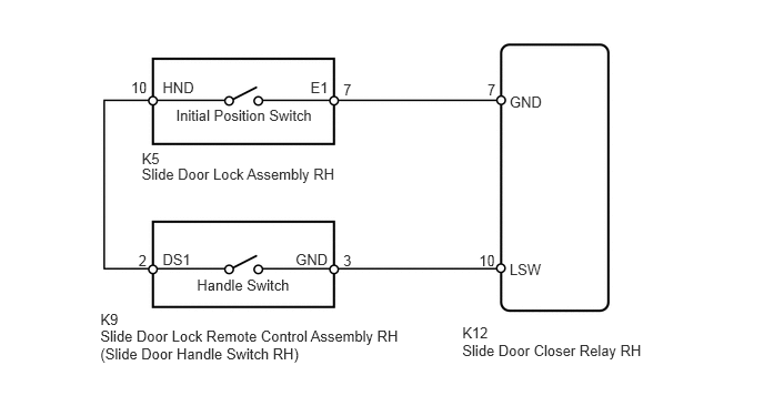
1.847,2.598 2.756,2.737
0.909,0.140
10
Handle Switch
1.651,1.001 2.979,1.140
1.328,0.140
10
Initial Position Switch
3.22,2.36 3.334,2.499
0.114,0.139
10
3
3.22,0.757 3.334,0.896
0.114,0.139
10
7
4.572,0.757 4.686,0.896
0.114,0.139
10
7
4.493,2.368 4.686,2.507
0.193,0.139
10
10
1.299,2.36 1.412,2.499
0.114,0.139
10
2
1.229,0.744 1.412,0.883
0.183,0.139
10
10
4.78,2.444 5.126,2.608
0.346,0.164
10
LSW
4.78,0.87 5.126,1.034
0.346,0.164
10
GND
1.525,0.744 1.857,0.909
0.332,0.165
10
HND
2.912,0.744 3.105,0.909
0.193,0.165
10
E1
1.525,2.351 1.857,2.517
0.332,0.165
10
DS1
2.772,2.351 3.104,2.517
0.332,0.165
10
GND
1.329,1.556 3.216,1.694
1.887,0.137
10
Slide Door Lock Assembly RH
0.941,3.069 3.842,3.373
2.901,0.304
10
Slide Door Lock Remote Control Assembly RH (Slide Door Handle Switch RH)
1.329,1.411 1.538,1.558
0.209,0.147
10
K5
0.941,2.915 1.164,3.062
0.223,0.147
10
K9
4.336,3.205 6.122,3.361
1.786,0.156
10
Slide Door Closer Relay RH
4.336,3.046 4.637,3.210
0.300,0.164
10
K12
PROCEDURE
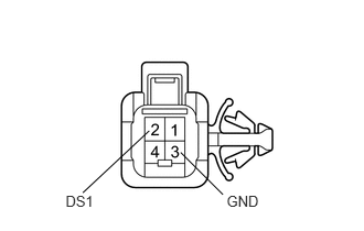
1.INSPECT SLIDE DOOR LOCK REMOTE CONTROL ASSEMBLY RH (SLIDE DOOR HANDLE SWITCH RH)
a.
0.619,1.825 0.962,2.016
0.343,0.191
10
DS1
2.14,1.825 2.504,1.988
0.364,0.163
10
GND
0.782,1.825 1.409,1.238
false
1.706,1.443 2.105,1.843
false
Remove the slide door lock remote control assembly RH.
b.
Measure the resistance of the slide door handle switch.
- Standard resistance:
Tester Connection Condition Specified Condition 2 (DS1) - 3 (GND) Handle pulled Below 1 Ω 2 (DS1) - 3 (GND) Handle not pulled 10 kΩ or higher
OK
2.INSPECT SLIDE DOOR LOCK ASSEMBLY RH
NG
REPLACE SLIDE DOOR LOCK REMOTE CONTROL ASSEMBLY RH
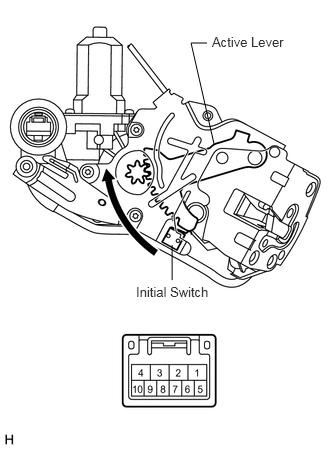
2.INSPECT SLIDE DOOR LOCK ASSEMBLY RH
a.
2.229,1.5 1.99,0.448
1.99,0.448 2.156,0.448
false
1.792,2.552 1.792,2.917
false
1.417,2.958 2.208,3.146
0.792,0.188
10
false
Initial Switch
2.208,0.354 3.042,0.51
0.833,0.156
10
false
Active Lever
Remove the slide door lock assembly RH.
b.
Measure the resistance of the slide door lock assembly.
- Standard resistance:
Tester Connection Condition Specified Condition 10 - 7 Initial position 10 kΩ or higher 10 - 7 Except initial position (slide door closer operating) Below 1 Ω
OK
3.CHECK WIRE HARNESS (SWITCH - ECU AND BODY GROUND)
NG
REPLACE SLIDE DOOR LOCK ASSEMBLY RH
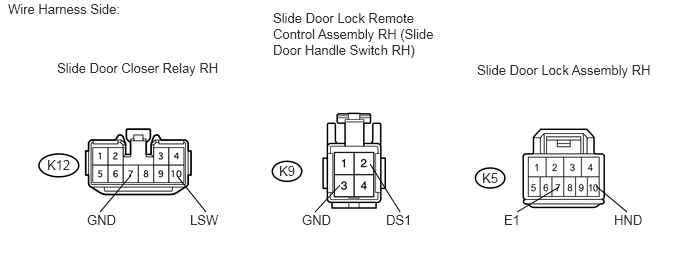
3.CHECK WIRE HARNESS (SWITCH - ECU AND BODY GROUND)
a.
Disconnect the K9 and K5 connectors.
6.208,1.938 6.531,2.208
false
5.823,1.948 5.385,2.208
false
1.844,1.833 2.146,2.208
false
1.365,1.823 1.042,2.208
false
3.542,1.927 3.281,2.208
false
3.854,1.708 4.167,2.208
false
0.083,0.01 1.385,0.156
1.302,0.146
10
false
Wire Harness Side:
0.594,0.625 2.375,0.76
1.781,0.135
10
false
Slide Door Closer Relay RH
2.844,0.104 4.646,0.583
1.802,0.479
10
false
Slide Door Lock Remote Control Assembly RH (Slide Door Handle Switch RH)
4.969,0.646 6.854,0.802
1.885,0.156
10
false
Slide Door Lock Assembly RH
0.49,1.635 0.781,1.802
0.292,0.167
10
false
K12
2.906,1.698 3.094,1.865
0.188,0.167
10
false
K9
5.021,1.771 5.208,1.938
0.188,0.167
10
false
K5
0.906,2.208 1.26,2.396
0.354,0.188
10
false
GND
5.25,2.208 5.469,2.396
0.219,0.188
10
false
E1
6.396,2.208 6.75,2.396
0.354,0.188
10
false
HND
1.979,2.208 2.333,2.396
0.354,0.188
10
false
LSW
3.146,2.208 3.5,2.396
0.354,0.188
10
false
GND
4.021,2.208 4.375,2.396
0.354,0.188
10
false
DS1
b.
Disconnect the K12 relay connector.
c.
Measure the resistance of the wire harness side connectors.
- Standard resistance:
Tester Connection Specified Condition K12-10 (LSW) - K9-3 (GND) Below 1 Ω K9-2 (DS1) - K5-10 (HND) Below 1 Ω K5-7 (E1) - K12-7 (GND) Below 1 Ω K12-10 (LSW) - Body ground 10 kΩ or higher K9-2 (DS1) - Body ground 10 kΩ or higher K5-7 (E1) - Body ground 10 kΩ or higher
OK
PROCEED TO NEXT CIRCUIT INSPECTION SHOWN IN PROBLEM SYMPTOMS TABLE
NG
REPAIR OR REPLACE HARNESS OR CONNECTOR