ENGINE HOOD / DOOR SLIDE DOOR CLOSER SYSTEM Slide Door Closer Position Switch LH Circuit
DESCRIPTION
The switch turns on when the slide door is opened and turns off when the door is closed. Slide door position state signals are input to the power slide door ECU*1 or slide door closer relay*2.
*1: w/ Power Slide Door LH
*2: w/o Power Slide Door LH
WIRING DIAGRAM
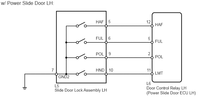
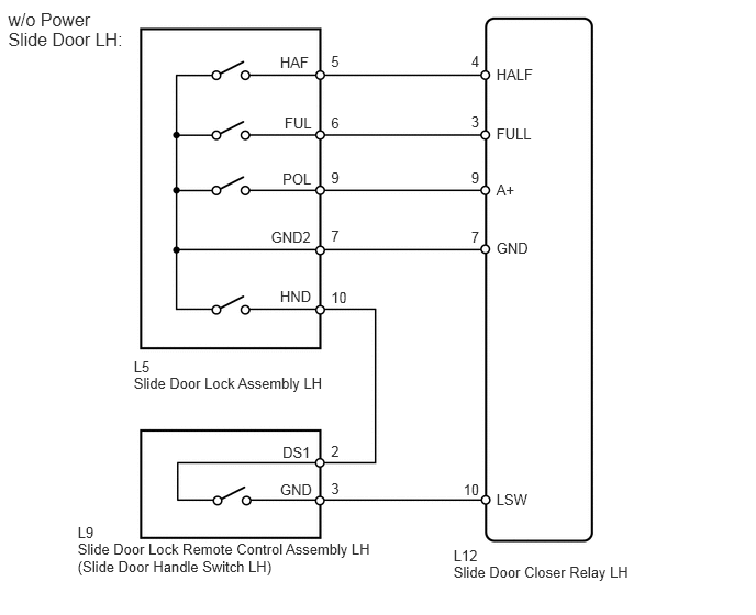
PROCEDURE
Check the vehicle specification.
- Result:
Result Proceed to w/ Power Slide Door LH A w/o Power Slide Door LH B
A
B
Use the Data List to check if the switch is functioning properly.
| Item | Measurement Item / Display (Range) | Normal Condition | Diagnosis Note |
|---|---|---|---|
| Pole Switch | Slide door lock pawl position switch signal / ON or OFF | ON: Slide door open to partially closed door or partially closed door to slide door closed
OFF: Slide door fully open, closed and partially closed |
- |
| Half Switch | Slide door lock half-latch switch signal / ON or OFF | ON: Slide door open to partially closed
OFF: Partially closed to fully closed |
- |
| Full Switch | Slide door lock full-latch switch signal / ON or OFF | ON: Slide door open to fully closed
OFF: Slide door fully closed |
- |
| Closer Position Switch | Slide door lock initial position switch signal / ON or OFF | ON: Slide door closer motor operating
OFF: Slide door closer motor stop (Initial position) |
- |
- OK:
When the switch is operating, the intelligent tester should display as shown in the table.
OK
NG
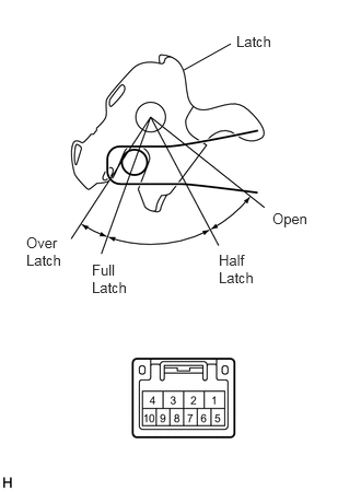
Remove the slide door lock assembly LH.
Measure the resistance of the half and full latch and pawl switch.
- Standard resistance:
- Half latch position:
Tester Connection Condition Specified Condition 6 - 7 Open Below 1 Ω 6 - 7 Half latch 10 kΩ or higher 6 - 7 Full latch 10 kΩ or higher 6 - 7 Over latch Below 1 Ω
- Full latch position:
Tester Connection Condition Specified Condition 5 - 7 Open Below 1 Ω 5 - 7 Half latch 10 kΩ or higher 5 - 7 Full latch 10 kΩ or higher 5 - 7 Over latch Below 1 Ω
- Pawl position:
Tester Connection Condition Specified Condition 9 - 7 Open Below 1 Ω 9 - 7 Half latch 10 kΩ or higher 9 - 7 Full latch 10 kΩ or higher 9 - 7 Over latch Below 1 Ω
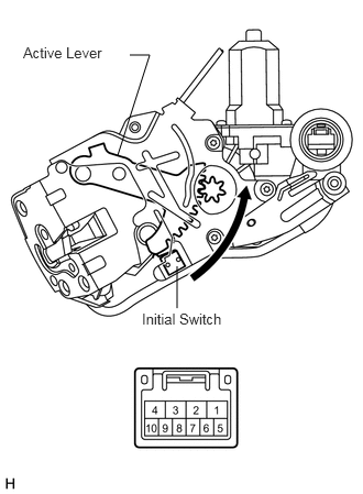
Measure the resistance of the initial switch.
- Standard resistance:
- Half latch position:
Tester Connection Condition Specified Condition 10 - 7 Initial position 10 kΩ or higher 10 - 7 Except initial position Below 1 Ω
OK
NG
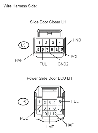
Disconnect the L5 slide door closer connector.
Disconnect the L6 ECU connector.
Measure the resistance of the wire harness side connectors.
- Standard resistance:
Tester Connection Specified Condition L5-6 (FUL) - L6-5 (FUL) Below 1 Ω L5-5 (HAF) - L6-12 (HAF) Below 1 Ω L5-9 (POL) - L6-2 (POL) Below 1 Ω L5-10 (HND) - L6-11 (LMT) Below 1 Ω L5-7 (GND2) - Body ground Below 1 Ω L5-6 (FUL) - Body ground 10 kΩ or higher L5-5 (HAF) - Body ground 10 kΩ or higher L5-9 (POL) - Body ground 10 kΩ or higher L5-10 (HND) - Body ground 10 kΩ or higher
OK
NG
Remove the slide door lock assembly LH.
Measure the resistance of the half and full latch and pawl switch.
- Standard resistance:
- Half latch position:
Tester Connection Condition Specified Condition 6 - 7 Open Below 1 Ω 6 - 7 Half latch 10 kΩ or higher 6 - 7 Full latch 10 kΩ or higher 6 - 7 Over latch Below 1 Ω
- Full latch position:
Tester Connection Condition Specified Condition 5 - 7 Open Below 1 Ω 5 - 7 Half latch 10 kΩ or higher 5 - 7 Full latch 10 kΩ or higher 5 - 7 Over latch Below 1 Ω
- Pawl position:
Tester Connection Condition Specified Condition 9 - 7 Open Below 1 Ω 9 - 7 Half latch 10 kΩ or higher 9 - 7 Full latch 10 kΩ or higher 9 - 7 Over latch Below 1 Ω
Measure the resistance of the initial switch.
- Standard resistance:
- Half latch position:
Tester Connection Condition Specified Condition 10 - 7 Initial position 10 kΩ or higher 10 - 7 Except initial position Below 1 Ω
OK
NG
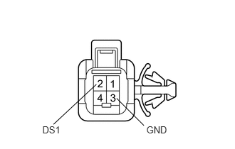
Remove the slide door lock remote control assembly LH.
Measure the resistance of the slide door handle switch.
- Standard resistance:
Tester Connection Condition Specified Condition 2 (DS1) - 3 (GND) Handle pulled Below 1 Ω 2 (DS1) - 3 (GND) Handle not pulled 10 kΩ or higher
OK
NG
Disconnect the L9 and L5 connectors.
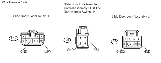
Disconnect the L12 relay connector.
Measure the resistance of the wire harness side connectors.
- Standard resistance:
Tester Connection Specified Condition L12-10 (LSW) - L9-3 (GND) Below 1 Ω L9-2 (DS1) - L5-10 (HND) Below 1 Ω L12-7 (GND) - L5-7 (GND2) Below 1 Ω L12-4 (HALF) - L5-5 (HAF) Below 1 Ω L12-3 (FULL) - L5-6 (FUL) Below 1 Ω L12-9 (A+) - L5-9 (POL) Below 1 Ω L12-10 (LSW) - Body ground 10 kΩ or higher L9-2 (DS1) - Body ground 10 kΩ or higher L12-7 (GND) - Body ground 10 kΩ or higher L12-4 (HALF) - Body ground 10 kΩ or higher L12-3 (FULL) - Body ground 10 kΩ or higher L12-9 (A+) - Body ground 10 kΩ or higher
OK
NG