Home › Vehicle Interior › ENGINE HOOD / DOOR › SLIDE DOOR CLOSER SYSTEM
RM24M0E _58 Vehicle Interior _059569 ENGINE HOOD / DOOR _0292020 SLIDE DOOR CLOSER SYSTEM J

ENGINE HOOD / DOOR  SLIDE DOOR CLOSER SYSTEM  Slide Door Closer Position Switch RH Circuit  


DESCRIPTION

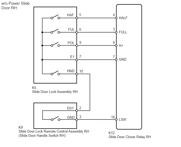
The switch turns on when the slide door is opened and turns off when the door is closed. Slide door position state signals are input to the power slide door ECU*1 or slide door closer relay*2.

*1: w/ Power Slide Door RH

*2: w/o Power Slide Door RH


WIRING DIAGRAM
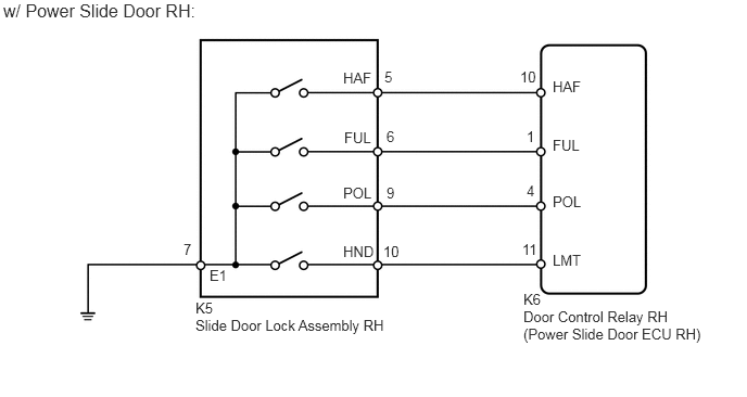
B138844E14
3.708,1.229 3.927,1.406 0.219,0.177 10 false 6 3.688,0.656 3.906,0.833 0.219,0.177 10 false 5 3.708,1.771 3.927,1.948 0.219,0.177 10 false 9 1.76,2.313 1.979,2.49 0.219,0.177 10 false 7 3.677,2.333 3.896,2.51 0.219,0.177 10 false 10 4.99,0.656 5.208,0.833 0.219,0.177 10 false 10 5.052,1.229 5.271,1.406 0.219,0.177 10 false 1 5.052,1.75 5.271,1.927 0.219,0.177 10 false 4 5.01,2.313 5.229,2.49 0.219,0.177 10 false 11 1.875,2.875 2.115,3.031 0.24,0.156 10 false K5 1.875,3.042 3.771,3.188 1.896,0.146 10 false Slide Door Lock Assembly RH 5.021,2.792 5.25,2.99 0.229,0.198 10 false K6 5.021,2.958 6.792,3.323 1.771,0.365 10 false Door Control Relay RH (Power Slide Door ECU RH) 5.302,0.75 5.688,0.927 0.385,0.177 10 false HAF 5.302,1.313 5.688,1.49 0.385,0.177 10 false FUL 5.302,1.854 5.688,2.031 0.385,0.177 10 false POL 5.302,2.417 5.688,2.594 0.385,0.177 10 false LMT 3.292,0.667 3.677,0.844 0.385,0.177 10 false HAF 3.302,1.24 3.688,1.417 0.385,0.177 10 false FUL 3.292,1.771 3.677,1.948 0.385,0.177 10 false POL 3.292,2.333 3.677,2.51 0.385,0.177 10 false HND 2.01,2.563 2.26,2.74 0.25,0.177 10 false E1 0.031,0 1.896,0.167 1.865,0.167 12 false w/ Power Slide Door RH:

B222198E06
4.299,5.339 6.038,5.504 1.739,0.165 10 Slide Door Closer Relay RH 4.299,5.185 4.589,5.327 0.290,0.142 10 K12 0.736,5.124 3.652,5.429 2.916,0.305 10 Slide Door Lock Remote Control Assembly RH (Slide Door Handle Switch RH) 1.268,3.548 3.213,3.711 1.945,0.163 10 Slide Door Lock Assembly RH 1.268,3.401 1.483,3.564 0.215,0.163 10 K5 0.736,4.97 0.950,5.119 0.214,0.149 10 K9 4.705,4.657 5.033,4.809 0.327,0.151 10 LSW 4.705,2.275 5.033,2.427 0.327,0.151 10 GND 4.705,1.715 4.908,1.866 0.202,0.151 10 A+ 4.705,1.183 5.088,1.334 0.383,0.151 10 FULL 4.705,0.622 5.083,0.773 0.378,0.151 10 HALF 2.655,0.51 2.982,0.661 0.327,0.151 10 HAF 2.697,1.08 2.983,1.231 0.286,0.151 10 FUL 2.678,1.617 2.983,1.768 0.304,0.151 10 POL 2.781,2.163 2.983,2.315 0.202,0.151 10 E1 2.655,2.728 2.982,2.880 0.327,0.151 10 HND 2.655,4.209 2.982,4.360 0.327,0.151 10 DS1 2.655,4.569 2.982,4.720 0.327,0.151 10 GND 3.138,4.557 3.242,4.720 0.104,0.163 10 3 3.138,4.193 3.242,4.355 0.104,0.163 10 2 3.138,2.742 3.329,2.905 0.191,0.163 10 10 3.138,2.154 3.242,2.317 0.104,0.163 10 7 3.138,1.601 3.242,1.763 0.104,0.163 10 9 3.138,1.082 3.242,1.245 0.104,0.163 10 6 3.138,0.501 3.242,0.664 0.104,0.163 10 5 4.466,0.501 4.570,0.664 0.104,0.163 10 4 4.466,1.068 4.570,1.231 0.104,0.163 10 3 4.466,1.608 4.570,1.770 0.104,0.163 10 9 4.466,2.172 4.570,2.334 0.104,0.163 10 7 4.392,4.56 4.569,4.723 0.177,0.163 10 10 0.054,0.029 1.173,0.352 1.119,0.323 11 w/o Power Slide Door RH:

PROCEDURE

1.SYSTEM CHECK
a.

Check the vehicle specification.

Result:
Result Proceed to
w/ Power Slide Door RH A
w/o Power Slide Door RH B


A

2.READ VALUE USING INTELLIGENT TESTER (POSITION SWITCH)

B

5.INSPECT SLIDE DOOR LOCK ASSEMBLY RH
2.READ VALUE USING INTELLIGENT TESTER (POSITION SWITCH)
a.

Use the Data List to check if the switch is functioning properly.

Power slide door ECU RH
Item Measurement Item / Display (Range) Normal Condition Diagnosis Note
Pole Switch Slide door lock pawl position switch signal / ON or OFF ON: Slide door open to partially closed door or partially closed door to slide door closed
OFF: Slide door fully open, closed and partially closed
-
Half Switch Slide door lock half-latch switch signal / ON or OFF ON: Slide door open to partially closed
OFF: Partially closed to fully closed
-
Full Switch Slide door lock full-latch switch signal / ON or OFF ON: Slide door open to fully closed
OFF: Slide door fully closed
-
Closer Position Switch Slide door lock initial position switch signal / ON or OFF ON: Slide door closer motor operating
OFF: Slide door closer motor stop (Initial position)
-

OK:

When the switch is operating, the intelligent tester should display as shown in the table.


OK

PROCEED TO NEXT CIRCUIT INSPECTION SHOWN IN PROBLEM SYMPTOMS TABLE

NG

3.INSPECT SLIDE DOOR LOCK ASSEMBLY RH
a.
B137558E05
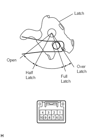
2.021,0.729 2.479,0.469 false 2.531,0.365 2.99,0.542 0.458,0.177 10 false Latch 2.615,2.167 3.073,2.573 0.458,0.406 10 false Over Latch 2.073,2.5 2.531,2.906 0.458,0.406 10 false Full Latch 0.875,2.375 1.333,2.781 0.458,0.406 10 false Half Latch 0.229,1.948 0.625,2.125 0.396,0.177 10 false Open

Remove the slide door lock RH.


b.

Measure the resistance of the half and full latch and pawl switch.

Standard resistance:
Half latch position:
Tester Connection Condition Specified Condition
6 - 7 Open Below 1 Ω
6 - 7 Half latch 10 kΩ or higher
6 - 7 Full latch 10 kΩ or higher
6 - 7 Over latch Below 1 Ω

Full latch position:
Tester Connection Condition Specified Condition
5 - 7 Open Below 1 Ω
5 - 7 Half latch 10 kΩ or higher
5 - 7 Full latch 10 kΩ or higher
5 - 7 Over latch Below 1 Ω

Pawl position:
Tester Connection Condition Specified Condition
9 - 7 Open Below 1 Ω
9 - 7 Half latch 10 kΩ or higher
9 - 7 Full latch 10 kΩ or higher
9 - 7 Over latch Below 1 Ω
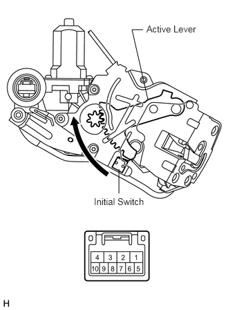


c.
B137559E05
2.229,1.5 1.99,0.448 1.99,0.448 2.156,0.448 false 1.792,2.552 1.792,2.917 false 1.417,2.958 2.208,3.146 0.792,0.188 10 false Initial Switch 2.208,0.354 3.042,0.51 0.833,0.156 10 false Active Lever

Measure the resistance of the initial switch.

Standard resistance:
Half latch position:
Tester Connection Condition Specified Condition
10 - 7 Initial position 10 kΩ or higher
10 - 7 Except initial position Below 1 Ω


OK

4.CHECK WIRE HARNESS (DOOR CLOSER - ECU AND BODY GROUND)

NG

REPLACE SLIDE DOOR LOCK ASSEMBLY RH

4.CHECK WIRE HARNESS (DOOR CLOSER - ECU AND BODY GROUND)
a.
U188696E02
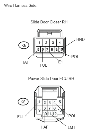
1.313,1.781 0.979,2.073 false 2.167,1.719 2.635,1.406 false 1.573,4.021 1.573,4.323 false 2.01,1.781 2.469,1.979 false 1.354,3.615 0.885,4.083 false 1.771,4.01 2.323,4.438 false 1.49,1.792 1.49,2.188 false 1.938,3.646 2.375,4.042 false 1.635,1.771 2.021,2.104 false 0.146,0.104 1.479,0.323 1.333,0.219 10 false Wire Harness Side: 1.073,0.688 2.49,0.833 1.417,0.146 10 false Slide Door Closer RH 0.99,2.677 2.76,2.823 1.771,0.146 10 false Power Slide Door ECU RH 0.75,1.51 0.979,1.677 0.229,0.167 10 false K5 0.719,3.5 0.948,3.667 0.229,0.167 10 false K6 0.604,4.021 0.948,4.188 0.344,0.167 10 false FUL 1.427,4.385 1.771,4.552 0.344,0.167 10 false HAF 1.396,2.208 1.74,2.375 0.344,0.167 10 false FUL 0.75,2.104 1.094,2.271 0.344,0.167 10 false HAF 2.375,4.396 2.719,4.563 0.344,0.167 10 false LMT 2.396,3.99 2.792,4.156 0.396,0.167 10 false POL 2.042,2.094 2.5,2.26 0.458,0.167 10 false E1 2.5,1.906 2.896,2.073 0.396,0.167 10 false POL 2.677,1.302 3.073,1.469 0.396,0.167 10 false HND

Disconnect the K5 slide door closer connector.


b.

Disconnect the K6 ECU connector.


c.

Measure the resistance of the wire harness side connectors.

Standard resistance:
Tester Connection Specified Condition
K5-6 (FUL) - K6-1 (FUL) Below 1 Ω
K5-5 (HAF) - K6-10 (HAF) Below 1 Ω
K5-9 (POL) - K6-4 (POL) Below 1 Ω
K5-10 (HND) - K6-11 (LMT) Below 1 Ω
K5-7 (E1) - Body ground Below 1 Ω
K5-6 (FUL) - Body ground 10 kΩ or higher
K5-5 (HAF) - Body ground 10 kΩ or higher
K5-9 (POL) - Body ground 10 kΩ or higher
K5-10 (HND) - Body ground 10 kΩ or higher


OK

REPLACE DOOR CONTROL RELAY RH (POWER SLIDE DOOR ECU RH)

NG

REPAIR OR REPLACE HARNESS OR CONNECTOR

5.INSPECT SLIDE DOOR LOCK ASSEMBLY RH
a.
B137558E05
2.021,0.729 2.479,0.469 false 2.531,0.365 2.99,0.542 0.458,0.177 10 false Latch 2.615,2.167 3.073,2.573 0.458,0.406 10 false Over Latch 2.073,2.5 2.531,2.906 0.458,0.406 10 false Full Latch 0.875,2.375 1.333,2.781 0.458,0.406 10 false Half Latch 0.229,1.948 0.625,2.125 0.396,0.177 10 false Open

Remove the slide door lock RH.


b.

Measure the resistance of the half and full latch and pawl switch.

Standard resistance:
Half latch position:
Tester Connection Condition Specified Condition
6 - 7 Open Below 1 Ω
6 - 7 Half latch 10 kΩ or higher
6 - 7 Full latch 10 kΩ or higher
6 - 7 Over latch Below 1 Ω

Full latch position:
Tester Connection Condition Specified Condition
5 - 7 Open Below 1 Ω
5 - 7 Half latch 10 kΩ or higher
5 - 7 Full latch 10 kΩ or higher
5 - 7 Over latch Below 1 Ω

Pawl position:
Tester Connection Condition Specified Condition
9 - 7 Open Below 1 Ω
9 - 7 Half latch 10 kΩ or higher
9 - 7 Full latch 10 kΩ or higher
9 - 7 Over latch Below 1 Ω


c.
B137559E05
2.229,1.5 1.99,0.448 1.99,0.448 2.156,0.448 false 1.792,2.552 1.792,2.917 false 1.417,2.958 2.208,3.146 0.792,0.188 10 false Initial Switch 2.208,0.354 3.042,0.51 0.833,0.156 10 false Active Lever

Measure the resistance of the initial switch.

Standard resistance:
Half latch position:
Tester Connection Condition Specified Condition
10 - 7 Initial position 10 kΩ or higher
10 - 7 Except initial position Below 1 Ω


OK

6.INSPECT SLIDE DOOR LOCK REMOTE CONTROL ASSEMBLY RH (SLIDE DOOR HANDLE SWITCH RH)

NG

REPLACE SLIDE DOOR LOCK ASSEMBLY RH

6.INSPECT SLIDE DOOR LOCK REMOTE CONTROL ASSEMBLY RH (SLIDE DOOR HANDLE SWITCH RH)
a.
B142338E06
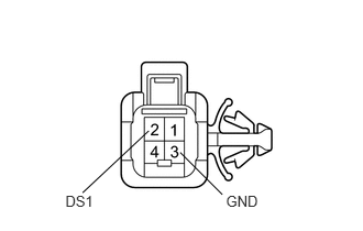
0.619,1.825 0.962,2.016 0.343,0.191 10 DS1 2.14,1.825 2.504,1.988 0.364,0.163 10 GND 0.782,1.825 1.409,1.238 false 1.706,1.443 2.105,1.843 false

Remove the slide door lock remote control assembly RH.


b.

Measure the resistance of the slide door handle switch.

Standard resistance:
Tester Connection Condition Specified Condition
2 (DS1) - 3 (GND) Handle pulled Below 1 Ω
2 (DS1) - 3 (GND) Handle not pulled 10 kΩ or higher


OK

7.CHECK WIRE HARNESS (SLIDE DOOR CLOSER RELAY - SLIDE DOOR LOCK AND HANDLE SWITCH)

NG

REPLACE SLIDE DOOR LOCK REMOTE CONTROL ASSEMBLY RH

7.CHECK WIRE HARNESS (SLIDE DOOR CLOSER RELAY - SLIDE DOOR LOCK AND HANDLE SWITCH)
a.

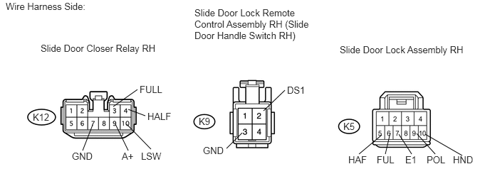
Disconnect the K9 and K5 connectors.

U188892E02
5.833,1.969 6.021,2.26 false 5.583,1.979 5.25,2.26 false 1.875,1.604 2.125,1.698 false 1.354,1.833 1.208,2.208 false 3.542,1.948 3.313,2.177 false 4.167,1.323 3.854,1.625 false 1.688,1.823 1.875,2.208 false 1.854,1.823 2.208,2.188 false 1.656,1.563 2.01,1.313 false 5.708,1.948 5.635,2.26 false 6.094,1.958 6.365,2.26 false 6.219,1.969 6.76,2.281 false 0.083,0.01 1.385,0.156 1.302,0.146 10 false Wire Harness Side: 0.594,0.625 2.365,0.76 1.771,0.135 10 false Slide Door Closer Relay RH 2.844,0.104 4.615,0.583 1.771,0.479 10 false Slide Door Lock Remote Control Assembly RH (Slide Door Handle Switch RH) 4.969,0.646 6.854,0.802 1.885,0.156 10 false Slide Door Lock Assembly RH 0.479,1.635 0.76,1.802 0.281,0.167 10 false K12 2.906,1.698 3.094,1.865 0.188,0.167 10 false K9 5.021,1.771 5.208,1.938 0.188,0.167 10 false K5 1.052,2.208 1.406,2.396 0.354,0.188 10 false GND 5.927,2.26 6.146,2.448 0.219,0.188 10 false E1 6.625,2.26 6.979,2.448 0.354,0.188 10 false HND 2.063,2.208 2.417,2.396 0.354,0.188 10 false LSW 2.156,1.625 2.531,1.813 0.375,0.188 10 false HALF 2.042,1.229 2.417,1.417 0.375,0.188 10 false FULL 1.781,2.208 1.979,2.396 0.198,0.188 10 false A+ 2.969,2.125 3.323,2.313 0.354,0.188 10 false GND 4.198,1.24 4.552,1.427 0.354,0.188 10 false DS1 6.24,2.26 6.552,2.448 0.313,0.188 10 false POL 5.51,2.26 5.813,2.448 0.302,0.188 10 false FUL 5.094,2.26 5.406,2.448 0.313,0.188 10 false HAF


b.

Disconnect the K12 relay connector.


c.

Measure the resistance of the wire harness side connectors.

Standard resistance:
Tester Connection Specified Condition
K12-10 (LSW) - K9-3 (GND) Below 1 Ω
K9-2 (DS1) - K5-10 (HND) Below 1 Ω
K12-7 (GND) - K5-7 (E1) Below 1 Ω
K12-4 (HALF) - K5-5 (HAF) Below 1 Ω
K12-3 (FULL) - K5-6 (FUL) Below 1 Ω
K12-9 (A+) - K5-9 (POL) Below 1 Ω
K12-10 (LSW) - Body ground 10 kΩ or higher
K9-2 (DS1) - Body ground 10 kΩ or higher
K12-7 (GND) - Body ground 10 kΩ or higher
K12-4 (HALF) - Body ground 10 kΩ or higher
K12-3 (FULL) - Body ground 10 kΩ or higher
K12-9 (A+) - Body ground 10 kΩ or higher


OK

PROCEED TO NEXT CIRCUIT INSPECTION SHOWN IN PROBLEM SYMPTOMS TABLE

NG

REPAIR OR REPLACE HARNESS OR CONNECTOR