RM24M0E
_58
Vehicle Interior
_059569
ENGINE HOOD / DOOR
_0292031
POWER BACK DOOR SYSTEM
U
ENGINE HOOD / DOOR POWER BACK DOOR SYSTEM TERMINALS OF ECU
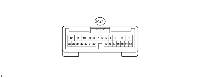
CHECK POWER BACK DOOR UNIT (POWER BACK DOOR ECU)
3.448,0.677 3.74,0.823
0.292,0.146
10
false
M24
a.
Disconnect the M24 ECU connector.
b.
Measure the voltage and resistance of the wire harness side connector.
| Symbols (Terminal No.) | Wiring Color | Terminal Description | Condition | Specified Condition |
|---|---|---|---|---|
| ECUB (M24-10) - Body ground | R - Body ground | ECUB power supply | Always | 10 to 14 V |
| B (M24-12) - Body ground | B - Body ground | B power supply | Always | 10 to 14 V |
| IG (M24-8) - Body ground | R - Body ground | IG power supply | Engine switch on (IG) | 10 to 14 V |
| IG (M24-8) - Body ground | R - Body ground | IG power supply | Engine switch off | Below 1 V |
| MSW (M24-17) - Body ground | LG - Body ground | Power back door main switch signal circuit | Power back door main switch not pushed | Below 1 Ω |
| MSW (M24-17) - Body ground | LG - Body ground | Power back door main switch signal circuit | Power back door main switch pushed | 10 kΩ or higher |
| FUL (M24-20) - Body ground | V - Body ground | Back door courtesy light switch signal circuit | Back door is opened | Below 1 Ω |
| FUL (M24-20) - Body ground | V - Body ground | Back door courtesy light switch signal circuit | Back door is closed | 10 kΩ or higher |
| DS1 (M24-4) - Body ground | L - Body ground | Back door closer switch signal circuit | Back door closer switch ON | Below 1 Ω |
| DS1 (M24-4) - Body ground | L - Body ground | Back door closer switch signal circuit | Back door closer switch OFF | 10 kΩ or higher |
| OSL (M24-15) - OSE (M24-14) | BR - LG | Power back door touch sensor LH circuit | Back door touch sensor LH not pressed | Approx. 1 kΩ |
| OSL (M24-15) - OSE (M24-14) | BR - LG | Power back door touch sensor LH circuit | Back door touch sensor LH pressed | Below 100 Ω |
| OSR (M24-13) - OSE (M24-14) | W - LG | Power back door touch sensor RH circuit | Back door touch sensor RH not pressed | Approx. 1 kΩ |
| OSR (M24-13) - OSE (M24-14) | W - LG | Power back door touch sensor RH circuit | Back door touch sensor RH pressed | Below 100 Ω |
| GND (M24-11) - Body ground | W-B - Body ground | Ground | Always | Below 1 Ω |
If the result is not as specified, there may be a malfunction on the wire harness side.
c.
Reconnect the M24 ECU connector.
d.
Measure the voltage of the connector.
| Symbols (Terminal No.) | Wiring Color | Terminal Description | Condition | Specified Condition |
|---|---|---|---|---|
| BZR+ (M24-26) - Body ground | R - Body ground | Power back door warning buzzer signal input | Back door warning buzzer is sounding | 10 to 14 V |
| BZR+ (M24-26) - Body ground | R - Body ground | Power back door warning buzzer signal input | Back door warning buzzer is stopped | Below 1 V |
| DC+ (M24-2) - DC- (M24-1) | B - R | Power back door lock motor circuit | Back door lock motor is operating | 10 to 14 V |
| DC+ (M24-2) - DC- (M24-1) | B - R | Power back door lock motor circuit | Back door lock motor is stopped | Below 1 V |
| CTYO (M24-3) - Body ground | R - Body ground | Luggage room light signal circuit | Luggage room light turn on | 10 to 14 V |
| CTYO (M24-3) - Body ground | R - Body ground | Luggage room light signal circuit | Luggage room light turns off | Below 1 V |
| HAF (M24-22) - Body ground | GR - Body ground | Back door lock half-latch switch signal circuit | Back door is opened →
Back door closer motor is operating → Back door is closed |
Below 1 V →
10 to 14 V → Below 1 V |
| POS (M24-24) - Body ground | P - Body ground | Back door lock position switch signal circuit | Back door is opened →
Back door closer motor is operating → Back door is closed |
Below 1 V →
10 to 14 V → Below 1 V |
If the result is not as specified, the ECU may have a malfunction.
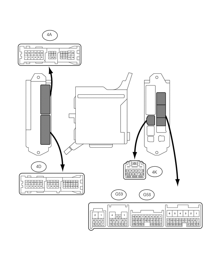
CHECK MAIN BODY ECU
4.75,6.385 5.177,6.635
0.427,0.25
10
false
G58
3.823,6.365 4.177,6.531
0.354,0.167
10
false
G59
5.042,5.635 5.344,5.813
0.302,0.177
10
false
4K
1.198,5.448 1.594,5.646
0.396,0.198
10
false
4D
1.552,1.063 1.885,1.333
0.333,0.271
10
false
4A
a.
Disconnect the 4A, 4K, G58 and G59 ECU connectors.
b.
Measure the voltage and resistance of the wire harness side connectors.
| Symbols (Terminal No.) | Wiring Color | Terminal Description | Condition | Specified Condition |
|---|---|---|---|---|
| BATB (4K-9) - Body ground | B - Body ground | +B power source circuit | Always | 10 to 14 V |
| PBDS (G58-2) - Body ground | LG - Body ground | Power back door open / close switch signal circuit | Power back door open / close switch ON | Below 1 Ω |
| PBDS (G58-2) - Body ground | LG - Body ground | Power back door open / close switch signal circuit | Power back door open / close switch OFF | 10 kΩ or higher |
| GND1 (G59-1) - Body ground | W-B - Body ground | Ground | Always | Below 1 Ω |
| GND2 (4A-3) - Body ground | W-B - Body ground | Ground | Always | Below 1 Ω |
If the result is not as specified, there may be a malfunction on the wire harness side.