RM24M0E
_58
Vehicle Interior
_059569
ENGINE HOOD / DOOR
_0292031
POWER BACK DOOR SYSTEM
J
ENGINE HOOD / DOOR POWER BACK DOOR SYSTEM Touch Sensor Circuit
DESCRIPTION
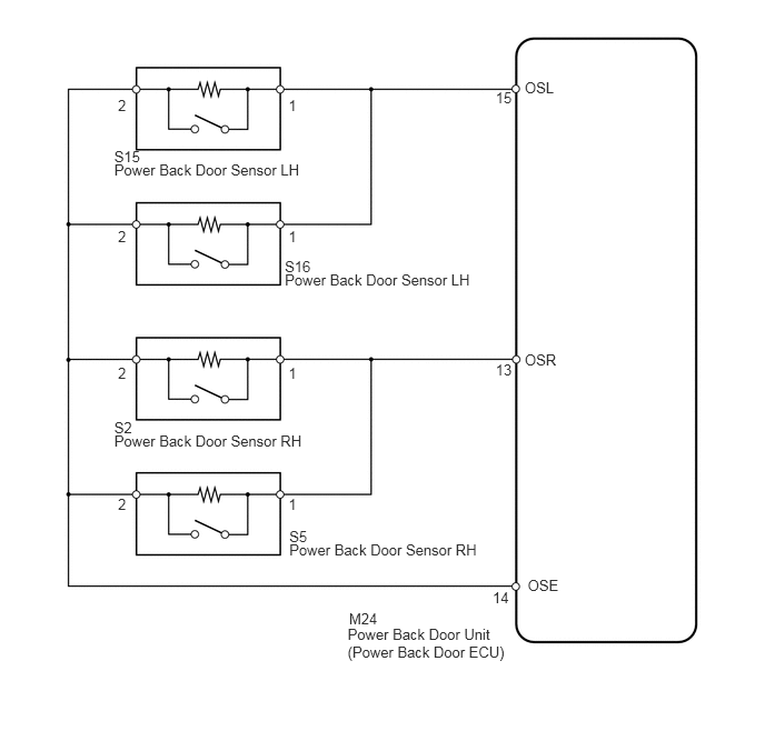
When the power back door ECU receives a jam signal from the touch sensor while the power back door closer is operating, the ECU reverses the back door operation and opens the door.
WIRING DIAGRAM
3.27,5.723 3.572,5.872
0.302,0.149
10
M24
4.944,5.408 5.301,5.557
0.357,0.149
10
OSE
4.615,5.52 4.806,5.683
0.191,0.163
10
14
4.916,3.292 5.357,3.476
0.441,0.184
10
OSR
4.643,0.833 4.910,1.017
0.267,0.184
10
15
4.916,0.735 5.357,0.919
0.441,0.184
10
OSL
4.643,3.39 4.910,3.574
0.267,0.184
10
13
1.105,0.91 1.254,1.080
0.149,0.170
10
2
2.703,4.644 2.851,4.814
0.149,0.170
10
1
1.105,3.418 1.254,3.588
0.149,0.170
10
2
1.105,2.136 1.254,2.306
0.149,0.170
10
2
2.703,0.91 2.851,1.080
0.149,0.170
10
1
1.105,4.644 1.254,4.814
0.149,0.170
10
2
2.703,3.418 2.851,3.588
0.149,0.170
10
1
2.703,2.136 2.851,2.306
0.149,0.170
10
1
2.71,4.945 4.525,5.094
1.816,0.149
10
S5
1.07,4.056 2.886,4.205
1.816,0.149
10
Power Back Door Sensor RH
1.07,3.93 2.886,4.079
1.816,0.149
10
S2
2.668,2.543 4.483,2.692
1.816,0.149
10
Power Back Door Sensor LH
2.668,2.416 4.483,2.565
1.816,0.149
10
S16
1.07,1.513 2.886,1.662
1.816,0.149
10
Power Back Door Sensor LH
1.07,1.387 2.886,1.536
1.816,0.149
10
S15
2.71,5.071 4.525,5.220
1.816,0.149
10
Power Back Door Sensor RH
3.256,5.863 4.822,6.193
1.566,0.330
10
Power Back Door Unit (Power Back Door ECU)
PROCEDURE
1.READ VALUE USING INTELLIGENT TESTER (POWER BACK DOOR TOUCH SENSOR)
a.
Check the Data List for proper functioning of the power back door touch sensor.
- Power back door unit (Power back door ECU):
Item Measurement Item / Display (Range) Normal Condition Diagnostic Note PBD Touch Sen L Power back door touch sensor LH signal / ON or OFF ON: Power back door touch sensor LH pressed
OFF: Power back door touch sensor LH not pressed- PBD Touch Sen R Power back door touch sensor RH signal / ON or OFF ON: Power back door touch sensor RH pressed
OFF: Power back door touch sensor RH not pressed-
- OK:
The display is as specified in the normal condition.
NG
2.INSPECT POWER BACK DOOR TOUCH SENSOR
OK
PROCEED TO NEXT CIRCUIT INSPECTION SHOWN IN PROBLEM SYMPTOMS TABLE
2.INSPECT POWER BACK DOOR TOUCH SENSOR
2.348,0.74 3.142,0.896
0.795,0.156
10
Not Pressed
2.468,2.396 3.059,2.552
0.591,0.156
10
Pressed
a.
Remove the power back door touch sensor.
b.
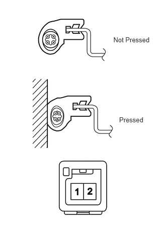
Measure the resistance of the sensor.
- Standard resistance:
Tester Connection Condition Specified Condition 1 - 2 Not pressed Approx. 1 kΩ 1 - 2 Pressed Below 100 Ω
OK
3.CHECK WIRE HARNESS (POWER BACK DOOR TOUCH SENSOR - POWER BACK DOOR UNIT AND BODY GROUND)
NG
REPLACE POWER BACK DOOR TOUCH SENSOR
3.CHECK WIRE HARNESS (POWER BACK DOOR TOUCH SENSOR - POWER BACK DOOR UNIT AND BODY GROUND)
0.135,3.801 0.433,3.957
0.298,0.156
10
M24
0.046,0.023 1.420,0.189
1.375,0.166
10
Wire Harness Side:
0.549,0.766 2.618,0.939
2.069,0.173
10
Power Back Door Touch Sensor
2.989,1.66 3.201,1.812
0.211,0.152
10
S2
2.358,2.055 2.638,2.208
0.281,0.152
10
S14
2.353,1.651 2.634,1.804
0.281,0.152
10
S15
2.968,2.072 3.179,2.225
0.211,0.152
10
S5
0.931,4.444 1.233,4.604
0.302,0.159
10
OSL
0.312,4.401 0.673,4.561
0.361,0.159
10
OSE
0.076,4.109 0.426,4.258
0.350,0.149
10
OSR
0.497,4.195 0.789,4.182
false
0.927,4.182 0.695,4.479
false
1.043,4.178 1.094,4.431
false
0.872,2.695 2.414,3.028
1.541,0.333
10
Power Back Door Unit (Power Back Door ECU)
a.
Disconnect the S15, S16, S2 and S5 sensor connectors.
b.
Disconnect the M24 ECU connector.
c.
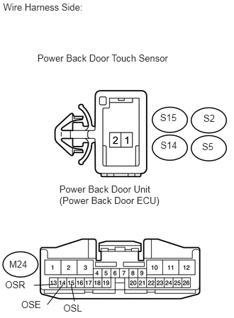
Measure the resistance of the wire harness side connectors.
- Standard resistance:
Tester Connection Specified Condition S15-1 - M24-15 (OSL) Below 1 Ω S15-2 - M24-14 (OSE) Below 1 Ω S16-1 - M24-15 (OSL) Below 1 Ω S16-2 - M24-14 (OSE) Below 1 Ω S2-1 - M24-13 (OSR) Below 1 Ω S2-2 - M24-14 (OSE) Below 1 Ω S5-1 - M24-13 (OSR) Below 1 Ω S5-2 - M24-14 (OSE) Below 1 Ω S15-1 - Body ground 10 kΩ or higher S15-2 - Body ground 10 kΩ or higher S16-1 - Body ground 10 kΩ or higher S16-2 - Body ground 10 kΩ or higher S2-1 - Body ground 10 kΩ or higher S2-2 - Body ground 10 kΩ or higher S5-1 - Body ground 10 kΩ or higher S5-2 - Body ground 10 kΩ or higher
OK
PROCEED TO NEXT CIRCUIT INSPECTION SHOWN IN PROBLEM SYMPTOMS TABLE
NG
REPAIR OR REPLACE HARNESS OR CONNECTOR