RM24M0E
_51
Engine / Hybrid System
_059570
CRUISE CONTROL
_0292039
CRUISE CONTROL SYSTEM
U
CRUISE CONTROL CRUISE CONTROL SYSTEM TERMINALS OF ECM
CHECK ECM
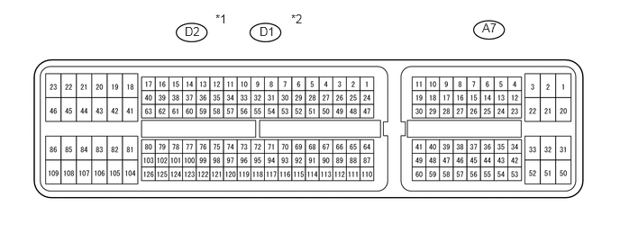
5.573,0.24 5.948,0.469
0.375,0.229
10
false
A7
2.135,0.281 2.365,0.438
0.229,0.156
10
false
D2
3,0.281 3.24,0.427
0.24,0.146
10
false
D1
2.49,0.135 2.719,0.292
0.229,0.156
10
false
*1
3.365,0.135 3.594,0.292
0.229,0.156
10
false
*2
- HINT:
-
As the ECM connector is a waterproof connector, it is not possible to check the voltage of each terminal or check the waveform with an oscilloscope while the ECM is installed in the vehicle.
| Symbols (Terminal No.) | Wiring Color | Terminal Description |
| D (D2-56)*1 | W | Shift position switch D |
| D (D1-26)*2 | L | Shift position switch D |
| E1 (D2-104)*1 | BR | ECM ground |
| E1 (D1-81)*2 | BR | ECM ground |
| SPD (A7-8) | B | Vehicle speed signal |
| SFTU (A7-16) | P | Shift position switch UP |
| TC (A7-27) | R | DTC output signal |
| ST1- (A7-35) | V | Cruise cancel input signal |
| SFTD (A7-51) | GR | Shift position switch DOWN |
- HINT:
- ·
*1: 2AZ-FE
·*2: 2GR-FE
a.
Disconnect the A7 and D2 or D1 connectors.
b.
Measure the voltage and resistance of the wire harness side connectors.
| Symbols (Terminal No.) | Wiring Color | Terminal Description | Condition | Specified Condition |
|---|---|---|---|---|
| STP (A7-36) - Body ground | L - Body ground | Stop light switch input signal | Depress brake pedal | 10 to 14 V |
| Release brake pedal | Below 1 V | |||
| CCS (A7-40) - E1 (D2-104)*1
CCS (A7-40) - E1 (D1-81)*2 |
V - BR | Cruise control main switch signal | CANCEL switch hold ON | 1,386 to 1,694 Ω |
| -/SET switch hold ON | 567 to 693 Ω | |||
| +/RES switch hold ON | 216 to 264 Ω | |||
| Main switch OFF | 10 kΩ or higher | |||
| Main switch ON | Below 1 Ω |
- HINT:
- ·
*1: 2AZ-FE
·*2: 2GR-FE
If the result is not as specified, there may be a malfunction on the wire harness side.