RM24M0E
_51
Engine / Hybrid System
_059570
CRUISE CONTROL
_0292039
CRUISE CONTROL SYSTEM
J
CRUISE CONTROL CRUISE CONTROL SYSTEM TC and CG Terminal Circuit
DESCRIPTION
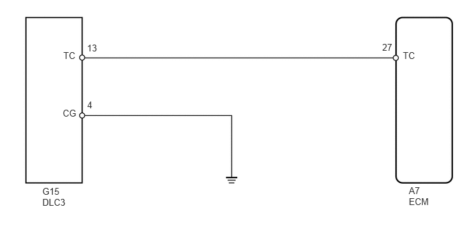
Connecting terminals 13 (TC) and 4 (CG) of the DLC3 enables DTCs to be read through blinking patterns of the combination meter's CRUISE main indicator light.
- HINT:
-
When a warning light of the combination meter blinks continuously, terminal 13 (TC) of the DLC3 or an ECM may have a ground short.
WIRING DIAGRAM
5.791,0.64 5.978,0.786
0.187,0.145
10
27
6.194,2.816 6.558,3.142
0.364,0.325
10
A7 ECM
1.318,0.642 1.502,0.791
0.184,0.149
10
13
0.959,0.763 1.170,0.978
0.211,0.215
10
TC
0.95,1.639 1.188,1.798
0.237,0.159
10
CG
1.32,1.509 1.451,1.667
0.132,0.158
10
4
0.642,2.821 1.056,3.169
0.415,0.348
10
G15 DLC3
6.104,0.758 6.352,0.942
0.248,0.184
10
TC
PROCEDURE
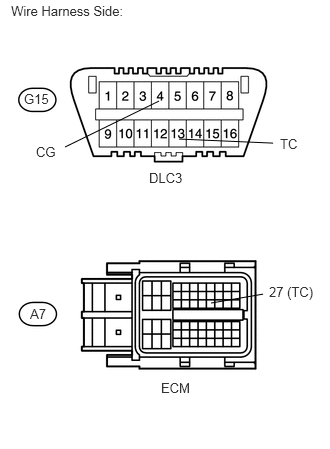
1.CHECK WIRE HARNESS (DLC3 - ECM AND BODY GROUND)
1.656,1.052 0.677,1.531
false
1.865,1.448 2.844,1.49
false
2.74,3.063 2.198,3.156
false
0.115,0.031 1.979,0.25
1.865,0.219
10
false
Wire Harness Side:
0.25,0.948 0.594,1.094
0.344,0.146
10
false
G15
2.917,1.417 3.156,1.604
0.24,0.188
10
false
TC
0.375,1.5 0.635,1.719
0.26,0.219
10
false
CG
1.552,1.771 1.969,1.958
0.417,0.188
10
false
DLC3
0.313,3.188 0.656,3.333
0.344,0.146
10
false
A7
2.802,2.958 3.302,3.146
0.5,0.188
10
false
27 (TC)
1.677,3.958 2.073,4.135
0.396,0.177
10
false
ECM
a.
Disconnect the G15 DLC3 connector.
b.
Disconnect the A7 ECM connector.
c.
Measure the resistance of the wire harness side connectors.
- Standard resistance:
Tester Connection Specified Condition G15-13 (TC) - A7-27 (TC) Below 1 Ω G15-13 (TC) or A7-27 (TC) - Body ground 10 kΩ or higher G15-4 (CG) - Body ground Below 1 Ω
OK
REPLACE ECM
NG
REPAIR OR REPLACE HARNESS OR CONNECTOR