CRUISE CONTROL CRUISE CONTROL SYSTEM P0571 Stop Light Switch Circuit Malfunction
DESCRIPTION
While driving with the cruise control on, if the ECM detects that the brake pedal is depressed, the cruise control operation will be canceled. The stop light switch sends brake pedal status signals to the ECM. When the brake pedal is not depressed, terminal ST1- is equal to the positive (+) battery voltage and terminal STP is below 1 V. When the brake pedal is depressed, the ECM cancels cruise control operation. The ECM outputs this DTC when the voltage of terminals ST1- and STP are both below 1 V for 0.5 seconds or more at the same time.
At this time, the set speed is erased, the cruise control operation is canceled, and the power indicator blinks until the main switch is pushed OFF. Cruise control operation is prohibited until the main switch is pushed ON again.
| DTC No. | DTC Detection Condition | Trouble Are |
|---|---|---|
| P0571 | When both conditions below are met:
·
Voltage of terminal STP is less than 1 V for 0.5 seconds or more ·
Voltage of terminal ST1 - is less than 1 V for 0.5 seconds or more |
·
Stop light switch circuit ·
Stop light switch ·
ECM |
WIRING DIAGRAM
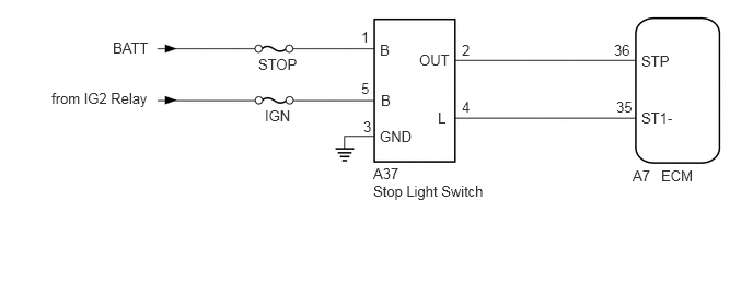
CAUTION / NOTICE / HINT
- HINT:
-
Inspect the fuses for circuits related to this system before performing the following inspection procedure.
PROCEDURE
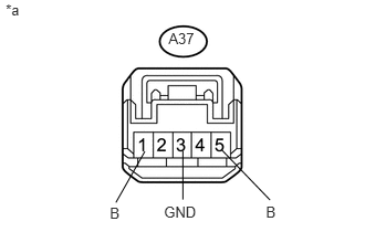
Disconnect the A37 stop light switch connector.
| *a | Front view of wire harness connector
(to Stop Light Switch) |
Measure the voltage according to the value(s) in the table below.
- Standard Voltage:
Tester Connection Condition Specified Condition A37-1 (B) - A37-3 (GND) Always 11 to 14 V A37-5 (B) - A37-3 (GND) Engine switch on (IG) 11 to 14 V
Measure the resistance according to the value(s) in the table below.
- Standard Resistance:
Tester Connection Condition Specified Condition A37-3 (GND) - Body ground Always Below 1 Ω
Reconnect the A37 stop light switch connector.
OK
NG
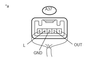
Measure the voltage according to the value(s) in the table below.
| *a | Component with harness connected
(Stop Light Switch) |
- Standard Voltage:
Tester Connection Condition Specified Condition A37-2 (OUT) - A37-3 (GND) Engine switch off, brake pedal not depressed Below 1 V Engine switch off, brake pedal depressed 11 to 14 V A37-4 (L) - A37-3 (GND) Engine switch on (IG), brake pedal not depressed 11 to 14 V Engine switch on (IG), brake pedal depressed Below 1 V
OK
NG
Disconnect the A7 ECM connector.
Disconnect the A37 stop light switch connector.
Measure the resistance according to the value(s) in the table below.
- Standard Resistance (Check for Open):
Tester Connection Condition Specified Condition A7-36 (STP) - A37-2 (OUT) Always Below 1 Ω A7-35 (ST1-) - A37-4 (L) Always Below 1 Ω
- Standard Resistance (Check for Short):
Tester Connection Condition Specified Condition A7-36 (STP) or A37-2 (OUT) - Body ground Always 10 kΩ or higher A7-35 (ST1-) or A37-4 (L) - Body ground Always 10 kΩ or higher
Reconnect the A37 stop light switch connector.
Reconnect the A7 ECM connector.
- Result:
Result Proceed to NG A OK
(for 2AZ-FE)B OK
(for 2GR-FE)C
A
B
C