Home › Engine / Hybrid System › 2GR-FE STARTING › SMART ENTRY AND START SYSTEM
RM24M0E _51 Engine / Hybrid System _059574 2GR-FE STARTING _0292072 SMART ENTRY AND START SYSTEM C

2GR-FE STARTING  SMART ENTRY AND START SYSTEM  B2287  LIN Communication Master Malfunction  


DESCRIPTION

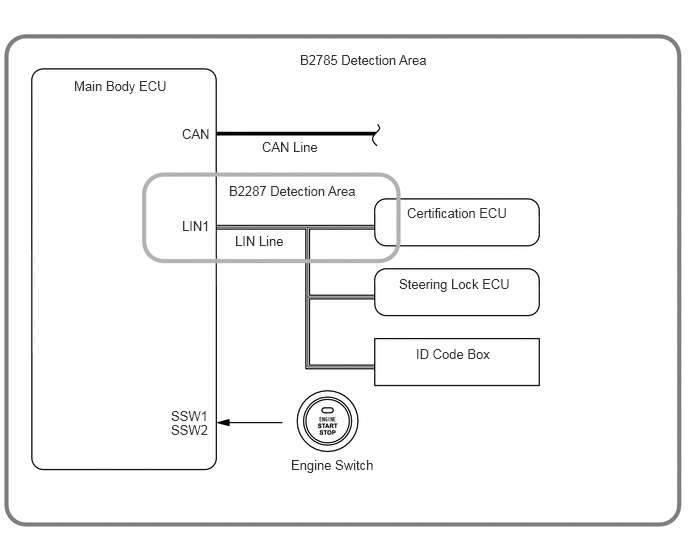
This DTC is output when there is a LIN communication problem between the main body ECU and certification ECU.

HINT:

When the main body ECU is replaced with a new one and the negative (-) battery terminal is connected, the power source mode becomes the IG-ON mode. When the battery is removed and reinstalled, the power source mode that was selected when the battery was removed is restored.

After the main body ECU or certification ECU is replaced, perform the registration procedures for the engine immobiliser system.


DTC No. DTC Detection Condition Trouble Area
B2287 Communication or communication line is abnormal between the main body ECU and the certification ECU
·

Instrument panel junction block LH (Main body ECU)

·

Certification ECU

·

Wire harness or connector


B460040E01
3.125,0.542 4.708,0.844 1.583,0.302 10 false B2785 Detection Area 0.771,0.813 1.865,1.125 1.094,0.313 10 false Main Body ECU 1.896,1.313 2.813,1.625 0.917,0.313 10 false CAN 2.729,1.448 3.646,1.76 0.917,0.313 10 false CAN Line 1.896,2.271 2.813,2.583 0.917,0.313 10 false LIN1 2.448,2.427 3.365,2.74 0.917,0.313 10 false LIN Line 2.385,1.906 3.896,2.198 1.51,0.292 10 false B2287 Detection Area 4.24,2.135 5.479,2.448 1.24,0.313 10 false Certification ECU 4.156,2.875 5.396,3.177 1.24,0.302 10 false Steering Lock ECU 4.333,3.604 5.25,3.917 0.917,0.313 10 false ID Code Box 3.031,4.76 4.115,5.073 1.083,0.313 10 false Engine Switch 1.781,4.25 2.698,4.563 0.917,0.313 10 false SSW1 1.781,4.396 2.698,4.708 0.917,0.313 10 false SSW2

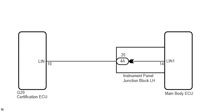
WIRING DIAGRAM

B137989E16
0.57,3.205 1.684,3.365 1.114,0.161 10 Certification ECU 0.577,3.067 0.862,3.209 0.286,0.142 10 G29 4.079,1.993 4.291,2.135 0.211,0.142 10 4A 1.301,1.998 1.549,2.140 0.248,0.142 10 LIN 5.648,1.993 5.965,2.135 0.317,0.142 10 LIN1 5.597,3.09 6.614,3.245 1.017,0.156 10 Main Body ECU 4.183,2.493 5.323,2.810 1.140,0.317 10 Instrument Panel Junction Block LH 5.414,2.082 5.593,2.233 0.179,0.152 10 14 1.603,2.082 1.782,2.233 0.179,0.152 10 10 4.107,1.781 4.309,1.933 0.202,0.152 10 20

PROCEDURE

1.CHECK FOR DTCS

b.

Check for DTC B2287 (LIN communication master malfunction) and B2785 (Communication malfunction between ECUs connected by LIN).

Result:
Display (DTC output) Proceed to
"DTC B2287" only A
"DTC B2287" and "DTC B2785" B
No DTC C


HINT:

If DTC B2785 is output, perform troubleshooting for DTC B2785 first (See page Vehicle Interior>ENGINE IMMOBILISER>ENGINE IMMOBILISER SYSTEM>B2785).


A

2.CHECK HARNESS AND CONNECTOR (MAIN BODY ECU - CERTIFICATION ECU)

B

C

CHECK INTERMITTENT PROBLEMS

2.CHECK HARNESS AND CONNECTOR (MAIN BODY ECU - CERTIFICATION ECU)
a.
U188867E02
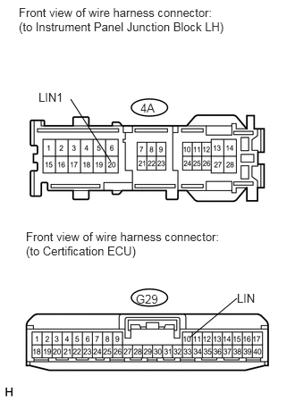
1.292,1.885 0.823,1.156 false 2.208,3.938 2.76,3.479 false 0.219,0.063 2.635,0.49 2.417,0.427 10 false Front view of wire harness connector: (to Instrument Panel Junction Block LH) 1.635,1.177 1.833,1.323 0.198,0.146 10 false 4A 0.448,1.052 0.771,1.198 0.323,0.146 10 false LIN1 2.76,3.396 3,3.542 0.24,0.146 10 false LIN 0.302,2.677 2.656,3 2.354,0.323 10 false Front view of wire harness connector: (to Certification ECU) 1.583,3.406 1.865,3.552 0.281,0.146 10 false G29

Disconnect the G29 and 4A ECU connectors.


b.

Measure the resistance according to the value(s) in the table below.

Standard resistance:
Tester Connection Condition Specified Condition
4A-20 (LIN1) - G29-10 (LIN) Always Below 1 Ω
4A-20 (LIN1) or G29-10 (LIN) - Body ground Always 10 kΩ or higher


OK

3.CHECK MAIN BODY ECU OPERATION

NG

REPAIR OR REPLACE HARNESS OR CONNECTOR

3.CHECK MAIN BODY ECU OPERATION
a.

After replacing the main body ECU with a normally functioning ECU, check that the engine starts.

OK:

Engine starts normally.


OK

END (MAIN BODY ECU DEFECTIVE)

NG

REPLACE CERTIFICATION ECU