2GR-FE STARTING SMART ENTRY AND START SYSTEM B2289 Key Collation Waiting Time Over
DESCRIPTION
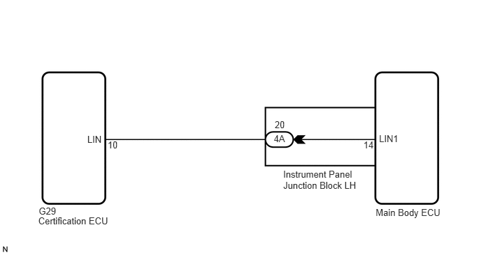
This DTC is output when there is a LIN communication problem between the main body ECU and certification ECU or when there is a problem in the entry function.
- HINT:
-
After the main body ECU is replaced, perform the registration procedures for the engine immobiliser system.
| DTC No. | DTC Detection Condition | Trouble Area |
|---|---|---|
| B2289 | Either condition below is met:
·
LIN communication is abnormal between the main body ECU and the certification ECU ·
The engine immobiliser system is malfunctioning |
·
Instrument panel junction block LH (Main body ECU) ·
Smart entry and start system (entry) ·
Wire harness or connector ·
Certification ECU |
WIRING DIAGRAM
PROCEDURE
Delete the DTCs (See page Engine / Hybrid System>2GR-FE STARTING>SMART ENTRY AND START SYSTEM>DTC CHECK / CLEAR).
Check for DTC B2289 (Key collection waiting time over) and B2785 (Communication malfunction between ECUs connected by LIN).
- Result:
Display (DTC output) Proceed to "DTC B2289" only A "DTC B2785" only B No DTC C
- HINT:
- ·
If DTC B2785 is output, perform troubleshooting for DTC B2785 first (See page Vehicle Interior>ENGINE IMMOBILISER>ENGINE IMMOBILISER SYSTEM>B2785).
A
B
C
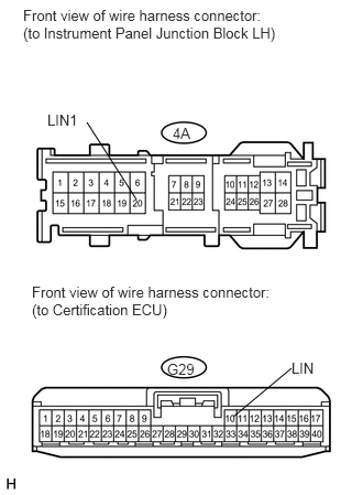
Disconnect the G29 and 4A ECU connectors.
Measure the resistance according to the value(s) in the table below.
- Standard resistance:
Tester Connection Condition Specified Condition 4A-20 (LIN1) - G29-10 (LIN) Always Below 1 Ω 4A-20 (LIN1) or G29-10 (LIN) - Body ground Always 10 kΩ or higher
OK
NG
After replacing the main body ECU with a normally functioning ECU, check that the engine starts.
- OK:
Engine starts normally.
- HINT:
-
If the engine does not start, refer to PROBLEM SYMPTOMS TABLE of the smart entry and start system (entry) (matching for the inside of the cabin cannot be performed) (See page Vehicle Interior>DOOR LOCK>SMART ENTRY AND START SYSTEM>Room Oscillator does not Recognize Key).
OK
NG