Home › Engine / Hybrid System › 2GR-FE STARTING › PUSH-BUTTON START
RM24M0E _51 Engine / Hybrid System _059574 2GR-FE STARTING _0292073 PUSH-BUTTON START J

2GR-FE STARTING  PUSH-BUTTON START  Power Source Mode does not Change to ON (ACC)  


DESCRIPTION

When the engine switch is pushed with the electrical key in the cabin, the main body ECU receives signals to switch the power source mode.

HINT:

To allow use of the GTS to inspect the push-button start function when the engine switch is off, repeat opening and closing any of the doors. Opening and closing a door establishes communication between the GTS and the main body ECU. (Opening and closing a door can also be simulated by operating a door courtesy light switch.)


WIRING DIAGRAM
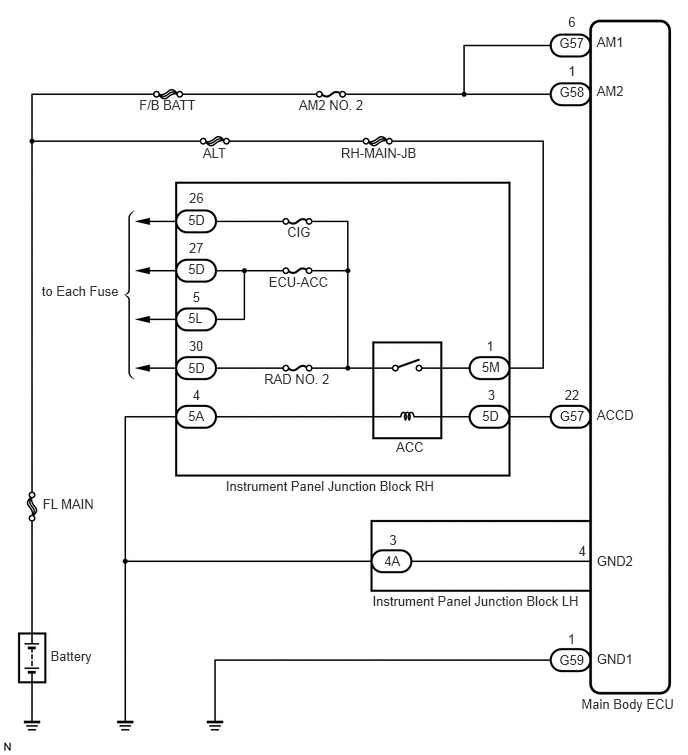
B168635E02
3.113,1.01 3.831,1.200 0.719,0.191 10 AM2 NO. 2 1.45,1.01 2.085,1.200 0.635,0.191 10 F/B BATT 3.552,1.515 4.391,1.705 0.839,0.191 10 RH-MAIN-JB 2.113,1.515 2.388,1.705 0.274,0.191 10 ALT 6.216,0.351 6.554,0.510 0.338,0.159 10 AM1 6.216,0.862 6.554,1.021 0.338,0.159 10 AM2 6.216,6.778 6.646,6.936 0.431,0.159 10 GND1 6.216,5.758 6.663,5.916 0.448,0.159 10 GND2 6.056,7.251 7.078,7.410 1.023,0.159 10 Main Body ECU 6.216,4.237 6.646,4.396 0.431,0.159 10 ACCD 5.826,0.365 6.120,0.531 0.295,0.166 10 G57 5.826,6.791 6.120,6.957 0.295,0.166 10 G59 5.83,4.248 6.124,4.414 0.295,0.166 10 G57 4.002,5.758 4.224,5.924 0.223,0.166 10 4A 5.882,4.029 6.084,4.195 0.202,0.167 10 22 5.914,6.569 6.043,6.736 0.129,0.167 10 1 6.026,5.658 6.155,5.825 0.129,0.167 10 4 4.056,5.538 4.185,5.705 0.129,0.167 10 3 5.023,4.248 5.245,4.414 0.223,0.166 10 5D 4.125,4.575 4.470,4.741 0.346,0.166 10 ACC 0.435,2.952 1.297,3.118 0.862,0.166 10 to Each Fuse 2.352,4.976 4.623,5.142 2.271,0.166 10 Instrument Panel Junction Block RH 3.88,6.174 6.108,6.340 2.228,0.166 10 Instrument Panel Junction Block LH 5.081,4.029 5.189,4.175 0.108,0.147 10 3 1.96,4.25 2.155,4.416 0.195,0.166 10 5A 0.526,6.746 1.008,6.912 0.482,0.166 10 Battery 0.445,5.171 1.045,5.337 0.600,0.166 10 FL MAIN 2.007,4.033 2.108,4.199 0.101,0.167 10 4 1.96,3.745 2.155,3.911 0.195,0.166 10 5D 2.752,3.862 3.475,4.028 0.723,0.166 10 RAD NO. 2 2.799,2.851 3.457,3.017 0.658,0.166 10 ECU-ACC 2.991,2.336 3.269,2.502 0.278,0.166 10 CIG 1.968,3.52 2.147,3.687 0.180,0.167 10 30 1.96,3.227 2.155,3.393 0.195,0.166 10 5L 2.007,3.007 2.108,3.173 0.101,0.167 10 5 1.96,2.722 2.155,2.888 0.195,0.166 10 5D 1.968,2.502 2.147,2.669 0.180,0.167 10 27 1.96,2.204 2.155,2.370 0.195,0.166 10 5D 1.97,1.984 2.145,2.151 0.175,0.167 10 26 5.019,3.738 5.242,3.904 0.223,0.166 10 5M 5.067,3.52 5.196,3.687 0.129,0.167 10 1 5.828,0.874 6.123,1.040 0.295,0.166 10 G58 5.919,0.657 6.048,0.823 0.129,0.167 10 1 5.919,0.151 6.048,0.318 0.129,0.167 10 6

PROCEDURE

1.INSPECT FUSE (AM2 NO. 2 AND F/B BATT)
a.

Remove the AM2 No. 2 and F/B BATT fuses from the engine room junction block No. 1.


b.

Remove the CIG, ECU-ACC and RAD No. 2 fuses from the instrument panel junction block RH.


c.

Measure the resistance of the fuse.

HINT:

When the fuse is shorted, check the system which is supplied the power through the shorted fuse, before replace it.


Standard resistance:

Below 1 Ω


OK

2.CHECK CONNECTORS

NG

REPLACE FUSE

2.CHECK CONNECTORS
a.

Check that the connectors are securely connected and the terminals are not deformed or loose.

OK:

The connectors are securely connected and the terminals are not deformed or loose.


OK

3.CHECK HARNESS AND CONNECTOR (MAIN BODY ECU - BATTERY)

NG

REPAIR OR REPLACE CONNECTORS

3.CHECK HARNESS AND CONNECTOR (MAIN BODY ECU - BATTERY)
a.

Disconnect the G57 and G58 main body ECU connectors.


b.

Measure the voltage according to the value(s) in the table below.

Standard voltage:
Tester Connection Condition Specified Condition
G57-6 (AM1) - Body ground Always 11 to 14 V
G58-1 (AM2) - Body ground Always 11 to 14 V


OK

4.CHECK HARNESS AND CONNECTOR (MAIN BODY ECU - BODY GROUND)

NG

REPAIR OR REPLACE HARNESS OR CONNECTOR

4.CHECK HARNESS AND CONNECTOR (MAIN BODY ECU - BODY GROUND)
a.

Disconnect the G59 main body ECU connector.


b.

Disconnect the 4A instrument panel junction block LH connector.


c.

Measure the resistance according to the value(s) in the table below.

Standard resistance:
Tester Connection Condition Specified Condition
G59-1 (GND1) - Body ground Always Below 1 Ω
4A-3 (GND2) - Body ground Always Below 1 Ω


OK

5.CHECK HARNESS AND CONNECTOR

NG

REPAIR OR REPLACE HARNESS OR CONNECTOR

5.CHECK HARNESS AND CONNECTOR
a.

Disconnect the 5D and 5A instrument panel junction block RH connectors.


b.

Measure the resistance according to the value(s) in the table below.

Standard resistance:
Tester Connection Condition Specified Condition
G57-22 (ACCD) - 5D-3 Always Below 1 Ω
G57-22 (ACCD) or 5D-3 - Body ground 10 kΩ or higher
5A-4 - Body ground Below 1 Ω


OK

6.CHECK HARNESS AND CONNECTOR

NG

REPAIR OR REPLACE HARNESS OR CONNECTOR

6.CHECK HARNESS AND CONNECTOR
a.

Disconnect the 5M instrument panel junction block RH connector.


b.

Measure the voltage according to the value(s) in the table below.

Standard voltage:
Tester Connection Condition Specified Condition
5M-1 - Body ground Always 11 to 14 V


OK

7.INSPECT INSTRUMENT PANEL JUNCTION BLOCK RH

NG

REPAIR OR REPLACE HARNESS OR CONNECTOR

7.INSPECT INSTRUMENT PANEL JUNCTION BLOCK RH
a.

Disconnect the 5L instrument panel junction block RH connector.


b.

Measure the resistance according to the value(s) in the table below.

Standard resistance:
Tester Connection Condition Specified Condition
5D-3 - 5A-4 Always Below 1 Ω
5D-3 or 5A-4- Body ground 10 kΩ or higher
5M-1 - 5D-26 When battery voltage is applied to 5D-3 and 5A-4 Below 1 Ω
5M-1 - 5D-27
5M-1 - 5D-30
5M-1 - 5L-5
5M-1 - Body ground 10 kΩ or higher
5M-1 - 5D-26 When battery voltage is not applied to 5D-3 and 5A-4 10 kΩ or higher
5M-1 - 5D-27
5M-1 - 5D-30
5M-1 - 5L-5


OK

REPLACE INSTRUMENT PENAL JUNCTION BLOCK LH

NG

REPLACE INSTRUMENT PANEL JUNCTION BLOCK RH