2AZ-FE STARTING SMART ENTRY AND START SYSTEM B2275 STSW Monitor Malfunction
DESCRIPTION
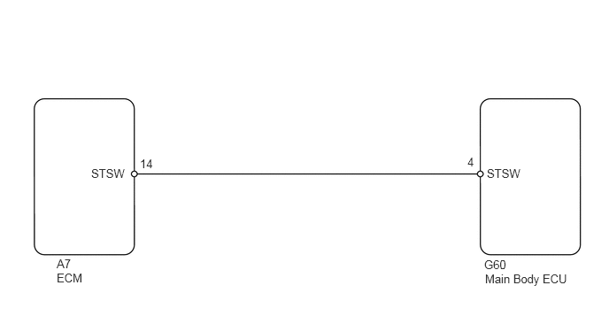
This DTC is output when the engine start request signal circuit inside the main body ECU is open or shorted.
| DTC No. | DTC Detection Condition | Trouble Area |
|---|---|---|
| B2275 | Engine start request signal circuit inside main body ECU or other related circuit is malfunctioning | ·
Main body ECU ·
SFI system ·
Wire harness |
WIRING DIAGRAM
PROCEDURE
Connect the intelligent tester to the DLC3.
Turn the ignition switch on (IG) and turn the tester ON.
Clear the DTCs.
Depress the brake pedal with the ignition switch on (IG), wait at least 15 seconds, and check whether DTC B2275 recurs.
- Result:
Display (DTC output) Proceed to B2275 A No DTC output B
A
B
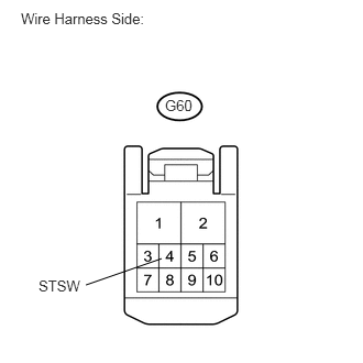
Disconnect the G60 main body ECU connector.
With the shift lever in P or N, depress the brake pedal fully.
Measure the voltage between the ECU terminal and the body ground when operating the engine switch to crank the engine.
- HINT:
-
The voltage is generated at terminal STSW for 0.3 seconds when the engine cranks.
- Standard voltage:
Tester Connection Specified Condition G60-4 (STSW) - Body ground 10 to 14 V
OK
NG
Disconnect the G60 main body ECU connector.
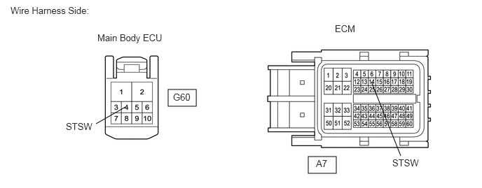
Disconnect the A7 ECM connector.
Check the resistance of the wire harness side connectors.
- Standard resistance:
Tester Connection Specified Condition G60-4 (STSW) - A7-14 (STSW) Below 1 Ω G60-4 (STSW) or A7-14 (STSW) - Body ground 10 kΩ or higher
OK
NG
Temporarily replace the main body ECU with a new or normally functioning one.
Check that the engine starts normally.
- OK:
Engine starts normally.
OK
NG
(See pageEngine / Hybrid System>2AZ-FE ENGINE CONTROL>SFI SYSTEM>HOW TO PROCEED WITH TROUBLESHOOTING)