Home › Engine / Hybrid System › 2AZ-FE STARTING › SMART ENTRY AND START SYSTEM
RM24M0E _51 Engine / Hybrid System _059575 2AZ-FE STARTING _0292080 SMART ENTRY AND START SYSTEM C

2AZ-FE STARTING  SMART ENTRY AND START SYSTEM  B2282  Vehicle Speed Signal Malfunction  B2283  Vehicle Speed Sensor Malfunction  


DESCRIPTION

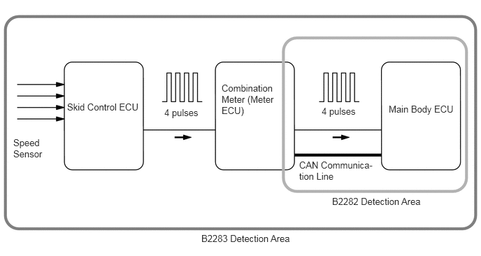
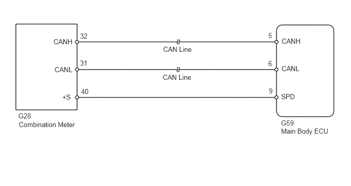
The main body ECU and the combination meter are connected with a cable and the CAN communication line. DTC B2282 is output when signals, transmitted through the cable and the communication line, do not match.

DTC No. DTC Detection Condition Trouble Area
B2282 Following conditions are met:
·

Signals between main body ECU and combination meter are inconsistent


·

Malfunction is detected in circuit between vehicle speed sensor and combination meter


·

Main body ECU


·

Combination meter


·

Wire harness


The skid control ECU converts these signals into 4-pulse signals and sends them to the combination meter. After these signals are converted into a more precise rectangular waveform by the waveform shaping circuit inside the combination meter, they are then transmitted to the main body ECU. The main body ECU determines the vehicle speed based on the frequencies of these pulse signals.

DTC No. DTC Detection Condition Trouble Area
B2283 When both conditions below are met:
·

Vehicle speed decreases significantly


·

Vehicle speed does not correspond with engine speed


·

Main body ECU


·

Combination meter


·

Speed sensor


·

Skid control ECU


·

Wire harness


A393971E01
2.448,1.594 3.188,1.865 0.74,0.271 10 false 4 pulses 1,1.51 2.177,1.813 1.177,0.302 10 false Skid Control ECU 3.302,1.229 4.115,1.854 0.813,0.625 10 false Combination Meter (Meter ECU) 5.792,1.542 6.875,1.792 1.083,0.25 10 false Main Body ECU 4.948,2.917 6.625,3.156 1.677,0.24 10 false B2282 Detection Area 4.458,2.375 5.583,2.76 1.125,0.385 10 false CAN Communica-tion Line 0.198,2.042 0.667,2.573 0.469,0.531 10 false Speed Sensor 3,3.469 4.677,3.688 1.677,0.219 10 false B2283 Detection Area 4.792,1.573 5.531,1.844 0.74,0.271 10 false 4 pulses

WIRING DIAGRAM

A395321E01
5.75,0.76 6.24,1.021 0.49,0.26 10 false CANH 5.75,1.323 6.24,1.583 0.49,0.26 10 false CANL 5.74,1.896 6.229,2.156 0.49,0.26 10 false SPD 1.271,1.906 1.76,2.167 0.49,0.26 10 false +S 0.375,2.292 0.865,2.552 0.49,0.26 10 false G28 0.385,2.469 1.719,2.75 1.333,0.281 10 false Combination Meter 5.74,2.438 6.229,2.698 0.49,0.26 10 false G59 5.74,2.604 6.833,2.865 1.094,0.26 10 false Main Body ECU 5.479,0.646 5.969,0.906 0.49,0.26 10 false 5 5.479,1.219 5.969,1.479 0.49,0.26 10 false 6 5.49,1.781 5.979,2.042 0.49,0.26 10 false 9 3.333,0.927 4.125,1.177 0.792,0.25 10 false CAN Line 1.635,0.656 2.125,0.917 0.49,0.26 10 false 32 1.635,1.208 2.125,1.469 0.49,0.26 10 false 31 1.656,1.792 2.146,2.052 0.49,0.26 10 false 40 1.094,0.771 1.583,1.031 0.49,0.26 10 false CANH 1.115,1.344 1.604,1.604 0.49,0.26 10 false CANL 3.323,1.5 4.115,1.75 0.792,0.25 10 false CAN Line

PROCEDURE

1.READ VALUE USING INTELLIGENT TESTER (VEHICLE SPEED SIGNAL)
a.

Connect the intelligent tester to the DLC3.


b.

Start the engine and turn the tester ON.


c.

Select the following menu items: Body / Main Body ECU / Data List / Vehicle Spd Sig.


d.

Read the display on the tester.

Main body ECU:
Item Measurement Item/Display (Range) Normal Condition Diagnostic Note
Vehicle Spd Sig Vehicle speed signal/ STOP or RUN STOP: Vehicle is stopped
RUN: Vehicle is running
-


OK:

STOP appears on screen.


NG

2.CHECK WIRE HARNESS (MAIN BODY ECU - COMBINATION METER)

OK

REPLACE MAIN BODY ECU

2.CHECK WIRE HARNESS (MAIN BODY ECU - COMBINATION METER)
a.

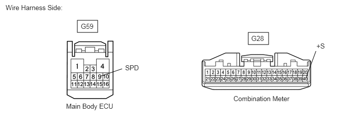
Disconnect the G59 main body ECU connector.
A393998E02
5.083,0.667 5.5,0.917 0.417,0.25 1.583,0.417 2,0.667 0.417,0.25 2.073,1.563 2.5,1.417 false 6.469,1.052 6.26,1.615 false 0.115,0.073 1.479,0.448 1.365,0.375 10 false Wire Harness Side: 4.781,1.948 6.083,2.417 1.302,0.469 10 false Combination Meter 2.563,1.313 3.125,1.563 0.563,0.25 10 false SPD 6.479,0.865 6.865,1.083 0.385,0.219 10 false +S 1.656,0.458 2.219,0.708 0.563,0.25 10 false G59 5.146,0.708 5.708,0.958 0.563,0.25 10 false G28 1.354,2.104 2.719,2.479 1.365,0.375 10 false Main Body ECU


b.

Disconnect the G28 combination meter connector.


c.

Measure the resistance of the wire harness side connectors.

Standard resistance:
Tester Connection Specified Condition
G59-9 (SPD) - G28-40 (+S) Below 1 Ω
G59-9 (SPD) or G28-40 (+S) - Body ground 10 kΩ or higher


OK

3.CHECK WHETHER ENGINE STARTS

NG

REPAIR OR REPLACE HARNESS OR CONNECTOR

3.CHECK WHETHER ENGINE STARTS
a.

Temporarily replace the main body ECU with a new or normally functioning one.


b.

Check that the engine starts normally.

OK:

Engine starts normally.


OK

END (MAIN BODY ECU IS FAULTY)

NG