Home › Engine / Hybrid System › 2AZ-FE STARTING › SMART ENTRY AND START SYSTEM
RM24M0E _51 Engine / Hybrid System _059575 2AZ-FE STARTING _0292080 SMART ENTRY AND START SYSTEM C

2AZ-FE STARTING  SMART ENTRY AND START SYSTEM  B2289  Key Collation Waiting Time Over  


DESCRIPTION

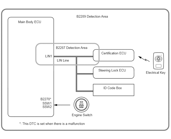
This DTC is output when there is a LIN communication problem between the main body ECU and certification ECU or when there is a problem in the engine immobiliser system.

DTC No. DTC Detection Condition Trouble Area
B2289 Either of following conditions is met:
·

Communication or communication line is abnormal among main body ECU, certification ECU, steering lock ECU and ID code box

·

Immobiliser system malfunctions


·

Main body ECU

·

Engine immobiliser system

·

Wire harness

·

Engine switch

·

Entry function

·

Electrical key


A393979E01
3.208,0.604 4.698,0.865 1.49,0.26 10 false B2289 Detection Area 0.76,0.833 1.927,1.094 1.167,0.26 10 false Main Body ECU 2.344,1.917 3.781,2.167 1.438,0.25 10 false B2287 Detection Area 1.896,2.271 2.417,2.521 0.521,0.25 10 false LIN1 2.385,2.448 2.958,2.698 0.573,0.25 10 false LIN Line 4.25,2.146 5.458,2.438 1.208,0.292 10 false Certification ECU 4.125,2.865 5.51,3.146 1.385,0.281 10 false Steering Lock ECU 4.333,3.604 5.167,3.844 0.833,0.24 10 false ID Code Box 6.115,2.958 7.01,3.229 0.896,0.271 10 false Electrical Key 3.01,4.74 4,4.99 0.99,0.25 10 false Engine Switch 0.813,5.104 4.115,5.406 3.302,0.302 10 false *: This DTC is set when there is a malfunction 1.698,4.073 2.219,4.323 0.521,0.25 10 false B2278* 1.781,4.25 2.302,4.5 0.521,0.25 10 false SSW1 1.781,4.396 2.302,4.646 0.521,0.25 10 false SSW2

WIRING DIAGRAM

A393977E03
1.26,1.958 1.844,2.208 0.583,0.25 10 false LIN 1.646,1.844 2.229,2.094 0.583,0.25 10 false 10 5.427,1.823 6.01,2.073 0.583,0.25 10 false 20 5.729,1.958 6.313,2.208 0.583,0.25 10 false LIN1 0.438,3.021 1.021,3.271 0.583,0.25 10 false G29 0.448,3.188 1.76,3.438 1.313,0.25 10 false Certification ECU 5.708,3.031 6.292,3.281 0.583,0.25 10 false 4A 5.708,3.198 6.771,3.458 1.063,0.26 10 false Main Body ECU

PROCEDURE

1.CHECK DTC

b.

Check for DTCs again.

OK:

DTC is not output.


NG

2.CHECK WIRE HARNESS (MAIN BODY ECU - CERTIFICATION ECU)

OK

END (SYSTEM OK)

2.CHECK WIRE HARNESS (MAIN BODY ECU - CERTIFICATION ECU)
a.
A394000E01
1.417,0.583 1.833,0.833 0.417,0.25 1.563,2.833 1.979,3.083 0.417,0.25 1.271,1.51 0.677,0.781 false 2.229,3.635 2.708,3.125 false 0.125,0.094 1.448,0.344 1.323,0.25 10 false Wire Harness Side: 0.323,0.688 0.938,0.885 0.615,0.198 10 false LIN1 1.531,0.615 2.146,0.813 0.615,0.198 10 false 4A 1.635,2.865 2.25,3.063 0.615,0.198 10 false G29 2.76,2.958 3.177,3.188 0.417,0.229 10 false LIN 1.302,4.229 2.594,4.479 1.292,0.25 10 false Certification ECU 1.229,2.01 2.521,2.26 1.292,0.25 10 false Main Body ECU

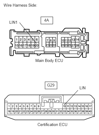
Disconnect the 4A main body ECU connector.


b.

Disconnect the G29 certification ECU connector.


c.

Measure the resistance of the wire harness side connectors.

Standard resistance:
Tester Connection Specified Condition
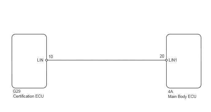
4A-20 (LIN1) - G29-10 (LIN) Below 1 Ω
4A-20 (LIN1) or G29-10 (LIN) - Body ground 10 kΩ or higher


OK

3.CHECK OPERATION OF MAIN BODY ECU

NG

REPAIR OR REPLACE HARNESS OR CONNECTOR

3.CHECK OPERATION OF MAIN BODY ECU
a.

Temporarily replace the main body ECU with a new or normally functioning one.


b.

Check for DTCs again.

OK:

DTC is not output.


NG

GO TO SMART ENTRY AND START SYSTEM (ROOM OSCILLATOR DOES NOT RECOGNIZE KEY)

OK

END (MAIN BODY ECU IS FAULTY)