RM24M0E
_51
Engine / Hybrid System
_059575
2AZ-FE STARTING
_0292081
PUSH-BUTTON START
C
2AZ-FE STARTING PUSH-BUTTON START B2271 Ignition Hold Monitor Malfunction
DESCRIPTION
This DTC is output when the IG output circuits inside the main body ECU are open or shorted.
| DTC No. | DTC Detection Condition | Trouble Area |
|---|---|---|
| B2271 | LH-IG relay 1 actuation circuit or IG2 relay actuation circuit inside main body ECU is abnormal | ·
Main body ECU ·
AM2 NO. 2 fuse ·
Wire harness |
WIRING DIAGRAM
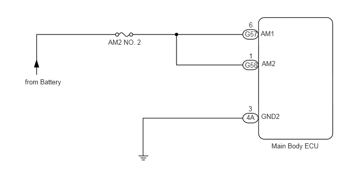
5.542,2.906 6.625,3.156
1.083,0.25
10
false
Main Body ECU
5,1.25 5.302,1.417
0.302,0.167
10
false
G58
5,0.615 5.302,0.781
0.302,0.167
10
false
G57
5.083,1.063 5.188,1.208
0.104,0.146
10
false
1
5.083,0.427 5.198,0.583
0.115,0.156
10
false
6
5.031,2.323 5.229,2.479
0.198,0.156
10
false
4A
5.073,2.146 5.188,2.292
0.115,0.146
10
false
3
2.208,0.781 2.969,1.031
0.76,0.25
10
false
AM2 NO. 2
0.51,1.594 1.406,1.781
0.896,0.188
10
false
from Battery
5.323,0.604 5.646,0.76
0.323,0.156
10
false
AM1
5.344,1.219 5.698,1.385
0.354,0.167
10
false
AM2
5.333,2.302 5.792,2.469
0.458,0.167
10
false
GND2
PROCEDURE
1.CHECK WHETHER DTC OUTPUT RECURS
a.
Connect the GTS to the DLC3.
b.
Turn the engine switch on (IG) and turn the tester ON.
c.
Clear the DTCs.
d.
Start the engine.
e.
Allow the engine to idle for 1 minute or more.
f.
Select the following menu items: Body Electrical / Body ECU / DTC.
g.
Read DTCs.
- Result:
Display (DTC output) Proceed to B2271 A No DTC output B
A
2.INSPECT FUSE (AM2 NO. 2)
B
END (SYSTEM IS OK)
2.INSPECT FUSE (AM2 NO. 2)
a.
Remove the AM2 NO. 2 fuse from the engine room No. 1 relay block.
b.
Measure the resistance of the fuse.
- Standard resistance:
Below 1 Ω
OK
3.CHECK WIRE HARNESS (MAIN BODY ECU - BATTERY AND BODY GROUND)
NG
REPLACE FUSE
3.CHECK WIRE HARNESS (MAIN BODY ECU - BATTERY AND BODY GROUND)
a.
Disconnect the G57, G58 and 4A main body ECU connectors.
b.
Measure the voltage and resistance of the wire harness side connectors.
- Standard voltage:
Tester Connection Specified Condition G58-1 (AM2) - Body ground 10 to 14 V G57-6 (AM1) - Body ground 10 to 14 V
- Standard resistance:
Tester Connection Specified Condition 4A-3 (GND2) - Body ground Below 1 Ω
OK
REPLACE MAIN BODY ECU
NG
REPAIR OR REPLACE HARNESS OR CONNECTOR