Home › Drivetrain › U660E (AUTOMATIC TRANSMISSION / TRANSAXLE) › AUTOMATIC TRANSAXLE SYSTEM
RM24M0E _52 Drivetrain _059579 U660E AUTOMATIC TRANSMISSION / TRANSAXLE _0292111 AUTOMATIC TRANSAXLE SYSTEM J

U660E AUTOMATIC TRANSMISSION / TRANSAXLE  AUTOMATIC TRANSAXLE SYSTEM  Park / Neutral Position Switch Circuit  


DESCRIPTION

The park/neutral position switch detects the shift lever position and sends signals to the TCM.

WIRING DIAGRAM
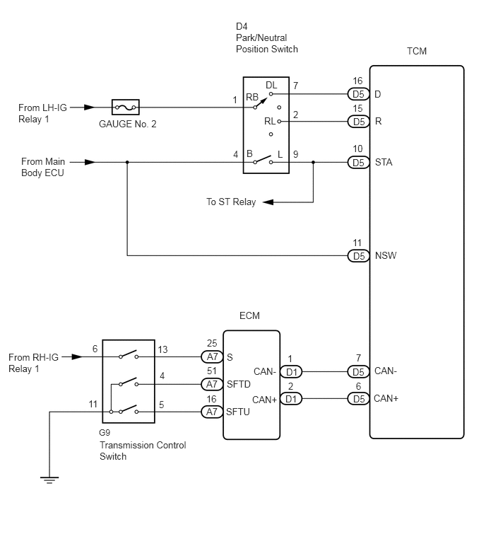
C157364E03
6,0.667 6.323,0.844 0.323,0.177 10 false TCM 3.479,0.302 4.438,0.813 0.958,0.51 10 false D4 Park/Neutral Position Switch 1.458,1.74 2.458,1.917 1,0.177 10 false GAUGE No. 2 3.042,2.885 3.833,3.063 0.792,0.177 10 false To ST Relay 0.271,1.5 1,1.885 0.729,0.385 10 false From LH-IG Relay 1 0.313,2.292 0.99,2.802 0.677,0.51 10 false From Main Body ECU 3.625,1.344 3.833,1.521 0.208,0.177 10 false RB 3.917,1.167 4.115,1.344 0.198,0.177 10 false DL 3.896,1.698 4.094,1.875 0.198,0.177 10 false RL 3.635,2.177 3.792,2.354 0.156,0.177 10 false B 4.094,2.188 4.25,2.365 0.156,0.177 10 false L 3.427,1.385 3.583,1.563 0.156,0.177 10 false 1 3.438,2.188 3.594,2.365 0.156,0.177 10 false 4 4.323,1.177 4.479,1.354 0.156,0.177 10 false 7 4.323,1.604 4.479,1.781 0.156,0.177 10 false 2 4.323,2.188 4.479,2.365 0.156,0.177 10 false 9 5.198,1.302 5.469,1.479 0.271,0.177 10 false D5 5.208,1.708 5.479,1.885 0.271,0.177 10 false D5 5.198,2.313 5.469,2.49 0.271,0.177 10 false D5 5.208,3.688 5.479,3.865 0.271,0.177 10 false D5 5.198,5.396 5.469,5.573 0.271,0.177 10 false D5 5.208,5.792 5.479,5.969 0.271,0.177 10 false D5 4.219,5.396 4.49,5.573 0.271,0.177 10 false D1 4.208,5.792 4.479,5.969 0.271,0.177 10 false D1 3.052,5.167 3.313,5.344 0.26,0.177 10 false A7 3.042,5.573 3.302,5.75 0.26,0.177 10 false A7 3.042,5.979 3.302,6.156 0.26,0.177 10 false A7 1.469,6.469 2.833,6.979 1.365,0.51 10 false Transmission Control Switch 2.323,5.063 2.531,5.24 0.208,0.177 10 false 13 2.354,5.448 2.51,5.625 0.156,0.177 10 false 4 2.344,5.875 2.5,6.052 0.156,0.177 10 false 5 1.365,5.052 1.521,5.229 0.156,0.177 10 false 6 1.302,5.865 1.5,6.042 0.198,0.177 10 false 11 3.531,4.563 3.854,4.74 0.323,0.177 10 false ECM 0.125,5.177 0.927,5.573 0.802,0.396 10 false From RH-IG Relay 1 3.344,5.177 3.5,5.354 0.156,0.177 10 false S 3.344,5.573 3.719,5.75 0.375,0.177 10 false SFTD 3.333,5.979 3.708,6.156 0.375,0.177 10 false SFTU 3.719,5.802 4.115,5.979 0.396,0.177 10 false CAN+ 3.74,5.385 4.094,5.563 0.354,0.177 10 false CAN- 5.51,5.781 5.906,5.958 0.396,0.177 10 false CAN+ 5.521,5.375 5.875,5.552 0.354,0.177 10 false CAN- 5.521,1.302 5.677,1.479 0.156,0.177 10 false D 5.531,1.698 5.688,1.875 0.156,0.177 10 false R 5.531,2.302 5.823,2.479 0.292,0.177 10 false STA 5.198,1.104 5.365,1.281 0.167,0.177 10 false 16 5.198,1.51 5.365,1.688 0.167,0.177 10 false 15 5.198,2.104 5.365,2.281 0.167,0.177 10 false 10 5.531,3.677 5.875,3.854 0.344,0.177 10 false NSW 5.198,3.49 5.365,3.667 0.167,0.177 10 false 11 5.25,5.188 5.406,5.365 0.156,0.177 10 false 7 5.25,5.604 5.406,5.781 0.156,0.177 10 false 6 4.24,5.198 4.396,5.375 0.156,0.177 10 false 1 4.25,5.604 4.406,5.781 0.156,0.177 10 false 2 3.052,4.969 3.219,5.146 0.167,0.177 10 false 25 3.052,5.375 3.219,5.552 0.167,0.177 10 false 51 3.042,5.792 3.208,5.969 0.167,0.177 10 false 16 1.458,6.292 1.74,6.469 0.281,0.177 9 false G9

CAUTION / NOTICE / HINT

DATA LIST


HINT:

According to the Data List displayed on the intelligent tester, you can read the value of switches, sensors, actuators and other items without removing any parts. Reading the Data List as the first step in troubleshooting is one method to save diagnostic time.


NOTICE:

In the table below, the values listed under "Normal Condition" are reference values. Do not depend solely on these reference values when deciding whether a part is faulty.


a.

Warm up the engine.


b.

Turn the ignition switch off.


c.

Connect the intelligent tester to the DLC3.


d.

Turn the ignition switch on (IG).


e.

Turn on the tester.


f.

Enter the following items: "Powertrain / ECT / Data List".


g.

According to the display on the tester, read "Data List".

Tester Display Measurement Item/Range Normal Condition Diagnostic Note
Neutral Position SW Signal PNP Switch Status/
ON or OFF
Shift lever position is;
P and N: ON
Except P and N: OFF
When the shift lever position displayed on the intelligent tester differs from the actual position, adjustment of the PNP switch or the shift cable may be incorrect.
Shift SW Status (R Range) PNP Switch Status/
ON or OFF
Shift lever position is;
R: ON
Except R: OFF
When the shift lever position displayed on the intelligent tester differs from the actual position, adjustment of the PNP switch or the shift cable may be incorrect.
Shift SW Status (P Range) PNP Switch Status/
ON or OFF
Shift lever position is;
P: ON
Except P: OFF
When the shift lever position displayed on the intelligent tester differs from the actual position, adjustment of the PNP switch or the shift cable may be incorrect.
Shift SW Status (N Range) PNP Switch Status/
ON or OFF
Shift lever position is;
N: ON
Except N: OFF
When the shift lever position displayed on the intelligent tester differs from the actual position, adjustment of the PNP switch or the shift cable may be incorrect.
Shift SW Status (D Range) PNP Switch Status/
ON or OFF
Shift lever position is;
D and S: ON
Except D and S: OFF
When the shift lever position displayed on the intelligent tester differs from the actual position, adjustment of the PNP switch or the shift cable may be incorrect.
Sports Mode Selection SW Sport Mode Select Switch Status/
ON or OFF
Shift lever position is;
S, "+" and "-": ON
Except S, "+" and "-": OFF
-


PROCEDURE

1.INSPECT PARK/NEUTRAL POSITION SWITCH ASSEMBLY
a.
C367266E01
0.25,1.667 0.583,1.917 0.333,0.25 1.167,1.594 0.958,1.188 0.958,1.188 0.76,1.188 false 1.354,1.594 0.979,0.917 0.979,0.917 0.771,0.917 false 1.583,1.594 2.031,0.917 2.031,0.917 2.198,0.917 false 1.927,1.604 2.177,1.188 2.177,1.188 2.344,1.188 false 0.844,2.667 1.031,2.667 1.031,2.667 1.24,2.021 false 2.396,2.771 2.135,2.771 2.135,2.771 1.396,2.031 false 2.479,2.49 2.219,2.49 2.219,2.49 1.75,2.031 false 0.146,0.073 1.656,0.333 1.51,0.26 10 false Component Side: 0.854,0.469 2.771,0.75 1.917,0.281 10 false Park/Neutral Position Switch 0.313,1.708 0.896,1.99 0.583,0.281 10 false D4 0.583,1.104 1.167,1.385 0.583,0.281 10 false B 0.563,0.833 1.146,1.115 0.583,0.281 10 false PL 2.26,0.844 2.844,1.125 0.583,0.281 10 false RL 2.396,1.104 2.979,1.385 0.583,0.281 10 false RB 2.594,2.406 3.177,2.688 0.583,0.281 10 false DL 2.469,2.677 3.052,2.958 0.583,0.281 10 false NL 0.667,2.583 1.25,2.865 0.583,0.281 10 false L

Disconnect the park/neutral position switch connector.


b.

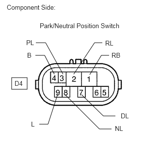
Measure the resistance according to the value(s) in the table below when the shift lever is moved to each position.

Standard resistance:
Tester Connection Shift Position Specified Condition
B (D4-4) - L (D4-9) P Below 1 Ω
Except P 10 kΩ or higher
RB (D4-1) - RL (D4-2) R Below 1 Ω
Except R 10 kΩ or higher
B (D4-4) - L (D4-9) N Below 1 Ω
Except N 10 kΩ or higher
RB (D4-1) - DL (D4-7) D, S, "+" and "-" Below 1 Ω
Except D, S, "+" and "-" 10 kΩ or higher


OK

2.INSPECT TRANSMISSION CONTROL SWITCH

NG

REPLACE PARK/NEUTRAL POSITION SWITCH ASSEMBLY

2.INSPECT TRANSMISSION CONTROL SWITCH
a.
U189452E02
0.135,0.073 1.552,0.625 1.417,0.552 10 false Switch Side: (Connector Front View) 1.573,1.219 1.885,1.396 0.313,0.177 10 false G9

Connect the park/neutral position switch connector.


b.

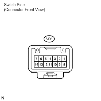
Disconnect the transmission control switch connector of the shift lock control unit assembly.


c.

Measure the resistance according to the value(s) in the table below when the shift lever is moved to each position.

Standard resistance:
Tester Connection Shift Position Specified Condition
G9-6 - G9-13 S, "+" and "-" Below 1 Ω
Except S, "+" and "-" 10 kΩ or higher


OK

3.CHECK ECU TERMINAL VOLTAGE (STA TERMINAL)

NG

REPLACE TRANSMISSION CONTROL SWITCH

3.CHECK ECU TERMINAL VOLTAGE (STA TERMINAL)
a.
U189038E02
1.5,1.396 1.281,1.927 true 0.042,0.021 1.292,0.219 1.25,0.198 10 false Wire Harness Side: 0.844,0.313 2.646,0.458 1.802,0.146 10 false TCM Connector (Front View) 0.188,0.781 0.458,0.927 0.271,0.146 10 false D5 1.146,1.948 1.438,2.094 0.292,0.146 10 false STA

Connect the transmission control switch connector of the shift lock control unit assembly.


b.

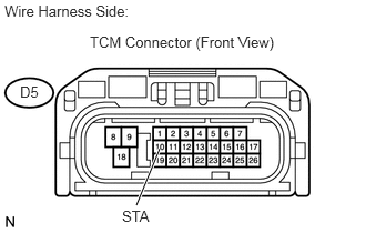
Measure the voltage according to the value(s) in the table below while cranking the engine.

Standard voltage:
Tester Connection Specified Condition
STA (D5-10) - Body ground 9 to 14 V


OK

4.CHECK HARNESS AND CONNECTOR (PARK/NEUTRAL POSITION SWITCH - TCM)

NG

REPAIR OR REPLACE HARNESS OR CONNECTOR (TCM - ECM)

4.CHECK HARNESS AND CONNECTOR (PARK/NEUTRAL POSITION SWITCH - TCM)
a.
U189039E02
2.125,1.396 1.906,1.927 true 2.26,1.406 2.417,1.938 true 0.031,0.021 1.292,0.24 1.26,0.219 10 false Wire Harness Side: 0.844,0.313 2.646,0.521 1.802,0.208 10 false TCM Connector (Front View) 0.188,0.781 0.458,0.927 0.271,0.146 10 false D5 1.854,1.948 1.99,2.094 0.135,0.146 10 false R 2.417,1.938 2.552,2.083 0.135,0.146 10 false D

Disconnect the TCM connector.


b.

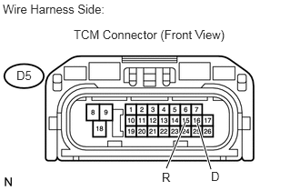
Turn the ignition switch on, and measure the voltage according to the value(s) in the table below when the shift lever is moved to each position.

Standard voltage:
Tester Connection Shift Position Specified Condition
R (D5-15) - Body ground R 10 to 14 V *
Except R Below 1 V
D (D5-16) - Body ground D 10 to 14 V
Except D Below 1 V


HINT:

*: The voltage will drop slightly because the back up light is turned on.


OK

REPLACE TCM

NG

REPAIR OR REPLACE HARNESS OR CONNECTOR (PARK/NEUTRAL POSITION SWITCH - TCM)