U660E AUTOMATIC TRANSMISSION / TRANSAXLE SHIFT SOLENOID VALVE REASSEMBLY
PROCEDURE

 1.INSTALL SHIFT SOLENOID VALVE SL4
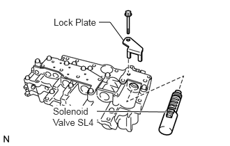
Coat the shift solenoid valve SL4 and bolt with ATF.
Install the shift solenoid valve SL4 and lock plate to the valve body assembly with the bolt.
- Torque:
- 11 N*m (112 kgf*cm, 8 ft.*lbf)
2.INSTALL SHIFT SOLENOID VALVE SL3
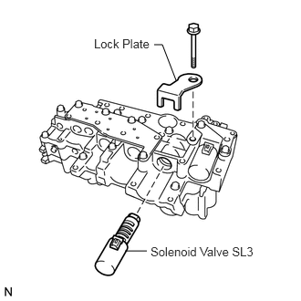
Coat the shift solenoid valve SL3 and bolt with ATF.
Install the shift solenoid valve SL3 and lock plate to the valve body assembly with the bolt.
- Torque:
- 11 N*m (112 kgf*cm, 8 ft.*lbf)
35210
3.INSTALL SHIFT SOLENOID VALVE SL1
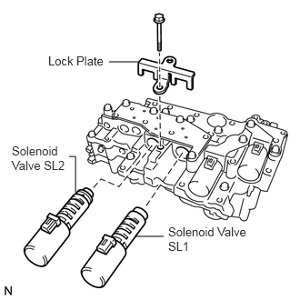
Coat the shift solenoid valve SL1 with ATF.
Install the shift solenoid valve SL1 to the valve body assembly.
35220
4.INSTALL SHIFT SOLENOID VALVE SL2
Coat the shift solenoid valve SL2 and bolt with ATF.
Install the shift solenoid valve SL2 and lock plate to the valve body assembly with the bolt.
- Torque:
- 11 N*m (112 kgf*cm, 8 ft.*lbf)
5.INSTALL SHIFT SOLENOID VALVE SLU
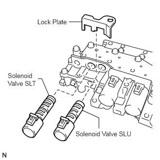
Coat the shift solenoid valve SLU with ATF.
Install the shift solenoid valve SLU to the valve body assembly.
6.INSTALL SHIFT SOLENOID VALVE SLT
Coat the shift solenoid valve SLT with ATF.
Install the shift solenoid valve SLT and lock plate to the valve body assembly.
7.INSTALL SHIFT SOLENOID VALVE SL
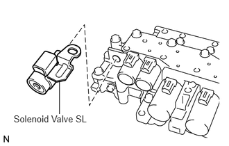
Coat the shift solenoid valve SL with ATF.
Install the shift solenoid valve SL to the valve body assembly.
8.INSTALL ATF TEMPERATURE SENSOR ASSEMBLY
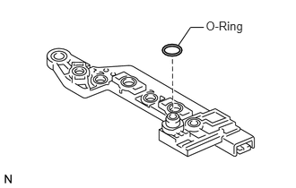
Coat a new O-ring with ATF and install it to the ATF temperature sensor assembly.
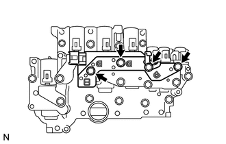
Coat the 4 bolts with ATF.
Install the ATF temperature sensor assembly and clamp to the valve body assembly with the 4 bolts.
- Torque:
- 11 N*m (112 kgf*cm, 8 ft.*lbf)
82125K
9.INSTALL TRANSMISSION WIRE
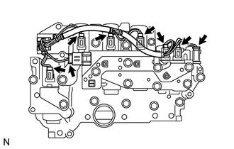
Connect the 8 connectors to the valve body assembly.
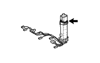
Coat the O-ring with ATF.
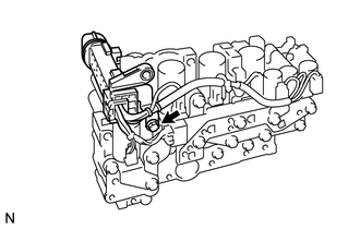
Coat the bolt with ATF.
Install the transmission wire and lock plate to the valve body assembly with the bolt.
- Torque:
- 11 N*m (112 kgf*cm, 8 ft.*lbf)