Home › Vehicle Interior › AIR CONDITIONING › AIR CONDITIONING SYSTEM
RM24M0E _58 Vehicle Interior _059584 AIR CONDITIONING _0292180 AIR CONDITIONING SYSTEM C

AIR CONDITIONING  AIR CONDITIONING SYSTEM  B1421/21  Solar Sensor Circuit (Passenger Side)  


DESCRIPTION
E107008E53
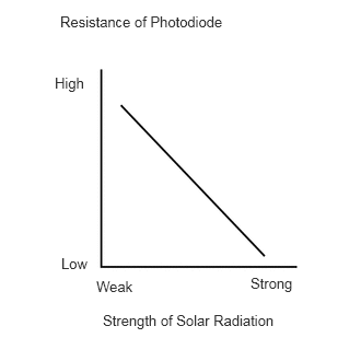
0.573,0.125 2.25,0.375 1.677,0.25 10 false Resistance of Photodiode 0.521,0.708 0.979,0.958 0.458,0.25 10 false High 0.583,2.427 1.042,2.698 0.458,0.271 10 false Low 0.917,2.646 1.438,2.896 0.521,0.25 10 false Weak 2.385,2.615 2.938,2.885 0.552,0.271 10 false Strong 0.979,2.969 2.719,3.208 1.74,0.24 10 false Strength of Solar Radiation

The solar sensor, which is installed on the upper side of the instrument panel, detects sunlight and controls the air conditioning AUTO mode. The output voltage from the solar sensor varies in accordance with the amount of sunlight. When the sunlight increases, the output voltage increases. As the sunlight decreases, the output voltage decreases. The air conditioning amplifier detects changes in the output voltage from the solar sensor.

DTC No. DTC Detection Condition Trouble Area
B1421/21 Open or short in passenger side solar sensor circuit
·

Solar sensor

·

Wire harness between solar sensor and air conditioning amplifier

·

Wire harness between solar sensor and main body ECU

·

Air conditioning amplifier


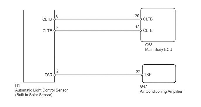
WIRING DIAGRAM

E127565E04
4.813,0.479 4.979,0.656 0.167,0.177 10 false 20 2,0.49 2.156,0.667 0.156,0.177 10 false 6 2.01,0.896 2.167,1.073 0.156,0.177 10 false 3 2.01,2.448 2.167,2.625 0.156,0.177 10 false 2 4.823,0.875 4.99,1.052 0.167,0.177 10 false 18 4.854,2.469 5.021,2.646 0.167,0.177 10 false 32 4.99,2.99 6.563,3.333 1.573,0.344 10 false G47 5.177,1.51 6.177,1.854 1,0.344 10 false G58 1.51,0.604 1.885,0.781 0.375,0.177 10 false CLTB 1.521,1.01 1.896,1.188 0.375,0.177 10 false CLTE 5.135,2.573 5.427,2.75 0.292,0.177 10 false TSP 5.104,0.594 5.479,0.771 0.375,0.177 10 false CLTB 5.104,1 5.479,1.177 0.375,0.177 10 false CLTE 1.594,2.583 1.885,2.76 0.292,0.177 10 false TSR 0.542,2.958 2.479,3.469 1.938,0.51 10 false H1 0.542,3.125 2.479,3.635 1.938,0.51 10 false Automatic Light Control Sensor (Built-in Solar Sensor) 4.99,3.167 6.781,3.448 1.792,0.281 10 false Air Conditioning Amplifier 5.177,1.677 6.323,1.99 1.146,0.313 10 false Main Body ECU

PROCEDURE

1.READ VALUE USING INTELLIGENT TESTER (SOLAR SENS-P)
a.

Connect the intelligent tester to the DLC3.


b.

Turn the ignition switch on (IG) and turn the intelligent tester main switch ON.


c.

Select the item below in the Data List, and read the value displayed on the intelligent tester.

Air conditioning amplifier:
Item Measurement Item / Display (Range) Normal Condition Diagnostic Note
Solar Sens-P Passenger side solar sensor /
Min.: 0, Max.: 255
Passenger side temperature increases as brightness increases -


OK:

The display is as specified in the normal condition column.


Result
Result Proceed to
NG A
OK (Checking from PROBLEM SYMPTOMS TABLE) B
OK (Checking from DTC) C


A

2.CHECK SOLAR SENSOR (SENSOR POWER INPUT)

B

PROCEED TO NEXT CIRCUIT INSPECTION SHOWN IN PROBLEM SYMPTOMS TABLE

C

REPLACE AIR CONDITIONING AMPLIFIER

2.CHECK SOLAR SENSOR (SENSOR POWER INPUT)
U189819E01
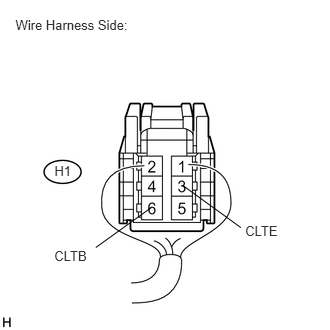
1.574,2.163 0.997,2.578 false 1.905,1.932 2.508,2.37 false 0.565,2.58 0.962,2.729 0.397,0.149 10 CLTB 2.554,2.324 2.951,2.517 0.397,0.193 10 CLTE 0.567,1.697 0.843,1.876 0.276,0.179 10 H1 0.161,0.175 1.444,0.363 1.283,0.188 10 Wire Harness Side:

a.

Disconnect the H1 solar sensor connector.


b.

Measure the voltage of the wire harness side connector.

Standard voltage:
Tester Connection Condition Specified Condition
H1-6 (CLTB) - H1-3 (CLTE) Ignition switch off Below 1 V
H1-6 (CLTB) - H1-3 (CLTE) Ignition switch on (IG) 10 to 14 V


NG

3.CHECK WIRE HARNESS (MAIN BODY ECU - SOLAR SENSOR)

OK

4.CHECK SOLAR SENSOR
3.CHECK WIRE HARNESS (MAIN BODY ECU - SOLAR SENSOR)
a.

Disconnect the G58 main body ECU connector.
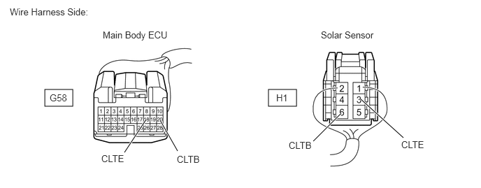
E358396E01
0.667,1.333 1.083,1.583 0.417,0.25 4,1.333 4.417,1.583 0.417,0.25 1.854,2.271 2.177,1.781 true 2.646,2.25 2.385,1.792 true 4.667,2.104 5.083,1.688 true 5.365,1.469 6.01,2.052 true 0.146,0.094 1.833,0.354 1.688,0.26 10 false Wire Harness Side: 1.531,0.438 2.76,0.729 1.229,0.292 10 false Main Body ECU 0.74,1.375 1.302,1.635 0.563,0.26 10 false G58 1.51,2.281 2.073,2.542 0.563,0.26 10 false CLTE 2.635,2.292 3.198,2.552 0.563,0.26 10 false CLTB 4.115,1.375 4.677,1.635 0.563,0.26 10 false H1 4.781,0.438 6.01,0.729 1.229,0.292 10 false Solar Sensor 5.979,2.073 6.542,2.333 0.563,0.26 10 false CLTE 4.302,2.083 4.865,2.344 0.563,0.26 10 false CLTB


b.

Disconnect the H1 solar sensor connector.

c.

Measure the resistance of the wire harness side connectors.

Standard resistance:
Tester Connection Specified Condition
G58-20 (CLTB) - H1-6 (CLTB) Below 1 Ω
G58-18 (CLTE) - H1-3 (CLTE) Below 1 Ω
G58-20 (CLTB) - Body ground 10 kΩ or higher
G58-18 (CLTE) - Body ground 10 kΩ or higher


OK

REPLACE MAIN BODY ECU

NG

REPAIR OR REPLACE HARNESS OR CONNECTOR

4.CHECK SOLAR SENSOR
a.
U189802E02
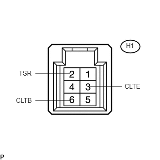
0.76,2.156 1.5,2.156 false 0.76,1.583 1.5,1.583 false 2.625,1.854 1.938,1.854 false 2.677,1.771 3.125,1.969 0.448,0.198 10 false CLTE 0.344,2.073 0.833,2.271 0.49,0.198 10 false CLTB 2.708,0.896 2.979,1.094 0.271,0.198 10 false H1 0.406,1.49 0.719,1.677 0.313,0.188 10 false TSR

Remove the solar sensor with its connector still connected.


b.

Connect the battery's positive (+) lead to terminal 6 (CLTB) and the negative (-) lead to terminal 3 (CLTE) of the solar sensor.


c.

Measure the voltage of the sensor.

Standard voltage:
Tester Connection Condition Specified Condition
H1-2 (TSR) - H1-3 (CLTE) Sensor is subjected to electric light 0.8 to 4.3 V
H1-2 (TSR) - H1-3 (CLTE) Sensor is covered with a cloth Below 0.8 V


NOTICE:
·

The connection procedure for using a digital tester such as a TOYOTA electrical tester is shown above. When using an analog tester, connect the negative (-) lead to terminal 6 and positive (+) lead to terminal 3 of the solar sensor.

·

While using the battery during inspection, do not bring the positive and negative tester probes too close to each other as a short circuit may occur.


HINT:
·

Use an incandescent light for inspection. Bring it within about 30 cm (11.8 in.) of the solar sensor.

·

As the inspection light is moved away from the sensor, the voltage increases.


OK

5.CHECK WIRE HARNESS (SOLAR SENSOR - AIR CONDITIONING AMPLIFIER)

NG

REPLACE SOLAR SENSOR

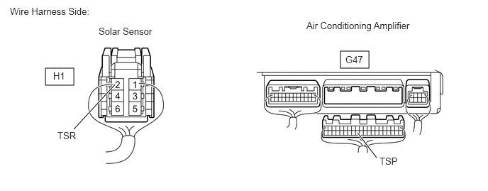
5.CHECK WIRE HARNESS (SOLAR SENSOR - AIR CONDITIONING AMPLIFIER)
a.

Disconnect the H1 solar sensor connector.

E358397E01
0.667,1 1.083,1.25 0.417,0.25 5,0.75 5.417,1 0.417,0.25 1.083,1.896 1.688,1.24 true 5.531,2.313 5.25,1.948 true 0.146,0.083 1.563,0.375 1.417,0.292 10 false Wire Harness Side: 1.448,0.375 2.51,0.719 1.063,0.344 10 false Solar Sensor 0.781,1.031 1.354,1.344 0.573,0.313 10 false H1 0.844,1.906 1.417,2.219 0.573,0.313 10 false TSR 4.5,0.292 6.208,0.646 1.708,0.354 10 false Air Conditioning Amplifier 5.073,0.792 5.646,1.104 0.573,0.313 10 false G47 5.573,2.281 6.146,2.594 0.573,0.313 10 false TSP


b.

Disconnect the G47 air conditioning amplifier connector.


c.

Measure the resistance of the wire harness side connectors.

Standard resistance:
Tester Connection Specified Condition
G47-32 (TSP) - H1-2 (TSR) Below 1 Ω
G47-32 (TSP) - Body ground 10 kΩ or higher


OK

REPLACE AIR CONDITIONING AMPLIFIER

NG

REPAIR OR REPLACE HARNESS OR CONNECTOR