Home › Vehicle Interior › AIR CONDITIONING › AIR CONDITIONING SYSTEM › from 2016.05
RM24M0E _58 Vehicle Interior _059584 AIR CONDITIONING _0292180 AIR CONDITIONING SYSTEM C

AIR CONDITIONING  AIR CONDITIONING SYSTEM  B1422/22  Compressor Lock Sensor Circuit  


SYSTEM DESCRIPTION

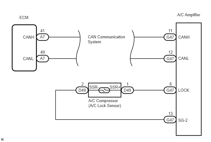
The ECM sends the engine speed signal to the A/C amplifier via CAN communication.

The A/C amplifier reads the difference between compressor speed and engine speed. When the difference becomes too large, the A/C amplifier determines that the compressor is locked, and turns the magnetic clutch off.

DTC No. DTC Detection Condition Trouble Area
B1422/22 Open or short in compressor lock sensor circuit
·

A/C compressor (A/C lock sensor)

·

Compressor drive belt

·

Harness or connector between compressor and A/C amplifier

·

A/C amplifier

·

CAN communication system


WIRING DIAGRAM

E147293E01
0.662,0.51 1.012,0.666 0.350,0.156 10 ECM 0.78,1.173 1.200,1.329 0.420,0.156 10 CANH 0.78,1.906 1.200,2.062 0.420,0.156 10 CANL 1.368,0.957 1.568,1.120 0.200,0.163 10 41 1.359,1.172 1.554,1.335 0.195,0.163 10 A7 1.368,1.685 1.568,1.848 0.200,0.163 10 49 1.359,1.9 1.563,2.063 0.205,0.163 10 A7 2.983,1.168 4.310,1.495 1.327,0.327 10 CAN Communication System 5.715,0.959 5.903,1.124 0.188,0.165 10 11 5.654,1.173 5.958,1.320 0.305,0.147 10 G47 5.654,1.908 5.958,2.055 0.305,0.147 10 G47 5.654,2.983 5.958,3.130 0.305,0.147 10 G47 5.654,3.991 5.958,4.138 0.305,0.147 10 G47 5.715,1.691 5.903,1.856 0.188,0.165 10 12 5.756,2.773 5.865,2.939 0.108,0.165 10 8 5.715,3.773 5.903,3.938 0.188,0.165 10 13 2.664,2.979 2.958,3.133 0.294,0.154 10 D49 4.201,2.979 4.496,3.133 0.294,0.154 10 D49 3.729,2.879 4.118,3.034 0.388,0.154 10 SSR+ 3.034,2.879 3.422,3.034 0.388,0.154 10 SSR- 3.003,3.329 4.173,3.664 1.169,0.335 10 A/C Compressor (A/C Lock Sensor) 4.293,2.773 4.402,2.932 0.109,0.158 10 1 2.764,2.773 2.874,2.932 0.109,0.158 10 2 6.054,3.995 6.408,4.151 0.353,0.156 10 SG-2 6.054,2.983 6.500,3.138 0.446,0.156 10 LOCK 6.054,1.901 6.500,2.057 0.446,0.156 10 CANL 6.054,1.174 6.500,1.329 0.446,0.156 10 CANH 6.019,0.416 6.863,0.589 0.844,0.173 10 A/C Amplifier

PROCEDURE

1.CHECK CAN COMMUNICATION SYSTEM
a.

Use the intelligent tester to check if the CAN communication system is functioning normally.

Result:
Result Proceed to
CAN DTC is not output A
CAN DTC is output B
(see page (Click here))


A

2.INSPECT AIR CONDITIONING AMPLIFIER

B

2.INSPECT AIR CONDITIONING AMPLIFIER
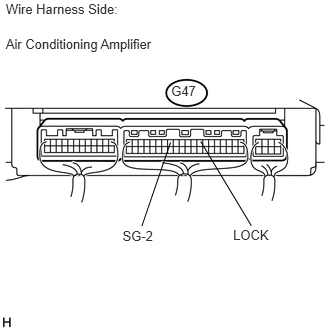
a.
U189817E01
0.06,0.374 1.667,0.554 1.608,0.180 10 Air Conditioning Amplifier 0.06,0.012 1.381,0.168 1.321,0.155 10 Wire Harness Side: 1.783,0.866 2.073,1.024 0.290,0.159 10 G47 2.428,2.367 2.839,2.523 0.411,0.156 10 LOCK 1.276,2.374 1.641,2.525 0.364,0.151 10 SG-2 2.09,1.473 2.617,2.35 false 1.776,1.483 1.477,2.355 false

Remove the A/C amplifier with the connectors still connected.

b.
E116941E03
0.099,0.947 0.463,1.144 0.364,0.198 10 GND 1.73,1.894 2.331,2.012 0.601,0.119 8 10 ms./DIV. 0.031,0.054 0.687,0.224 0.656,0.170 8 200 mV/DIV.

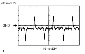
Measure the waveform of the connector.

Item Contents
Tool setting 200 mV/DIV., 10 ms./DIV.
Vehicle condition Engine is running
A/C switch: ON
Blower switch: LO

Standard:
Tester Connection Condition Specified Condition
G47-8 (LOCK) - G47-13 (SG-2) Engine is running
A/C switch: ON
Blower switch: LO
Pulse generation


Result:
Result Proceed to
NG A
OK (When troubleshooting according to the PROBLEM SYMPTOMS TABLE) B
OK (When troubleshooting according to the DTC) C


A

3.INSPECT COMPRESSOR AND MAGNETIC CLUTCH (A/C LOCK SENSOR)

B

PROCEED TO NEXT CIRCUIT INSPECTION SHOWN IN PROBLEM SYMPTOMS TABLE

C

REPLACE AIR CONDITIONING AMPLIFIER

3.INSPECT COMPRESSOR AND MAGNETIC CLUTCH (A/C LOCK SENSOR)
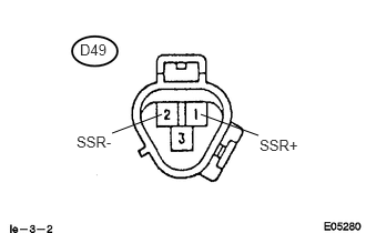
a.
U189796E02
1.521,1.073 1.052,1.25 false 1.885,1.073 2.427,1.271 false 0.75,0.385 1.042,0.542 0.292,0.156 10 false D49 0.719,1.25 1.115,1.406 0.396,0.156 10 false SSR- 2.438,1.281 2.833,1.438 0.396,0.156 10 false SSR+

Disconnect the connector from the A/C compressor.


b.

Measure the resistance according to the value(s) in the table below.

Standard resistance:
Tester Connection Condition Specified Condition
D49-1 (SSR+) - D49-2 (SSR-) 20°C (68°F) 160 to 320 Ω


OK

4.CHECK HARNESS AND CONNECTOR (A/C AMPLIFIER - A/C LOCK SENSOR)

NG

REPLACE COMPRESSOR AND MAGNETIC CLUTCH (A/C LOCK SENSOR)

4.CHECK HARNESS AND CONNECTOR (A/C AMPLIFIER - A/C LOCK SENSOR)
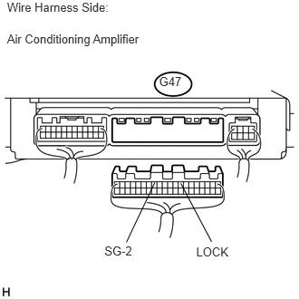
a.
U189815E01
2.078,2.108 2.432,2.779 false 1.779,2.098 1.453,2.785 false 2.255,2.815 2.707,2.975 0.452,0.161 10 LOCK 1.201,2.804 1.563,2.951 0.362,0.147 10 SG-2 0.081,0.361 1.688,0.541 1.608,0.180 10 Air Conditioning Amplifier 0.081,0 1.402,0.156 1.321,0.155 10 Wire Harness Side: 1.829,0.853 2.118,1.012 0.290,0.159 10 G47

Disconnect the connector from the A/C amplifier.

b.
U189814E01
0.082,0.039 1.602,0.195 1.520,0.156 10 Connector Front View: 0.082,0.473 2.184,0.643 2.102,0.170 10 Compressor and Magnetic Clutch 1.597,2.382 1.02,2.974 false 1.913,2.379 2.501,2.993 false 0.754,3.021 1.151,3.193 0.397,0.172 10 SSR+ 2.342,3.036 2.739,3.201 0.397,0.165 10 SSR- 0.557,2.251 0.846,2.409 0.290,0.159 10 D49

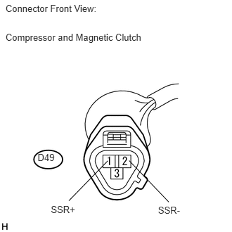
Measure the resistance according to the value(s) in the table below.

Standard resistance:
Tester Connection Condition Specified Condition
G47-8 (LOCK) - D49-1 (SSR+) Always Below 1 Ω
G47-13 (SG-2) - D49-2 (SSR-) Always Below 1 Ω
G47-8 (LOCK) - Body ground Always 10 kΩ or higher
G47-13 (SG-2) - Body ground Always 10 kΩ or higher


OK

REPLACE AIR CONDITIONING AMPLIFIER

NG

REPAIR OR REPLACE HARNESS OR CONNECTOR