Home › Vehicle Interior › AIR CONDITIONING › AIR CONDITIONING SYSTEM › 2013.04–2016.05
RM24M0E _58 Vehicle Interior _059584 AIR CONDITIONING _0292180 AIR CONDITIONING SYSTEM J

AIR CONDITIONING  AIR CONDITIONING SYSTEM  Blower Motor Circuit  


DESCRIPTION

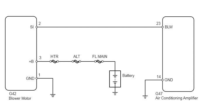
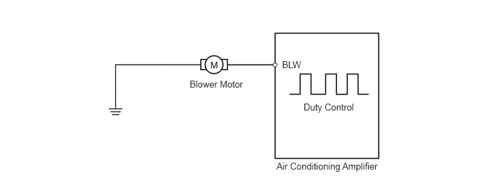
The blower motor is operated by signals from the air conditioning amplifier. Blower motor speed signals are transmitted in accordance with changes in the duty ratio.
E359917E01
2.844,1.177 3.875,1.479 1.031,0.302 10 false Blower Motor 4.229,0.885 5,1.188 0.771,0.302 10 false BLW 4.552,1.521 5.427,1.813 0.875,0.292 10 false Duty Control 4.146,2.406 5.948,2.656 1.802,0.25 10 false Air Conditioning Amplifier

WIRING DIAGRAM

E123559E16
5.875,0.875 6.229,1.208 0.354,0.333 10 false BLW 0.927,2.708 1.281,3.042 0.354,0.333 10 false GND 1.073,0.875 1.281,1.156 0.208,0.281 10 false SI 5.542,3.25 6.583,3.51 1.042,0.26 10 false G47 0.313,3.417 1.25,3.74 0.938,0.323 10 false Blower Motor 1.031,2.104 1.24,2.438 0.208,0.333 10 false +B 5.865,2.76 6.229,3.104 0.365,0.344 10 false GND 3.292,1.927 3.979,2.229 0.688,0.302 10 false FL MAIN 4.365,2.604 5.052,2.906 0.688,0.302 10 false Battery 1.802,1.927 2.188,2.229 0.385,0.302 10 false HTR 2.615,1.927 3,2.229 0.385,0.302 10 false ALT 5.573,0.75 5.802,0.917 0.229,0.167 10 false 23 1.396,1.969 1.625,2.135 0.229,0.167 10 false 3 1.375,0.75 1.604,0.917 0.229,0.167 10 false 2 1.365,2.583 1.594,2.75 0.229,0.167 10 false 1 5.583,2.646 5.813,2.813 0.229,0.167 10 false 14 5.542,3.406 7.104,3.667 1.563,0.26 10 false Air Conditioning Amplifier 0.323,3.25 1.26,3.573 0.938,0.323 10 false G42

PROCEDURE

1.PERFORM ACTIVE TEST USING INTELLIGENT TESTER (BLOWER MOTOR)
a.

Connect the intelligent tester to the DLC3.


b.

Turn the ignition switch on (IG) and turn the intelligent tester main switch ON.


c.

Select the item below in the Active Test, and then check that the blower motor operates.

Air conditioning amplifier:
Item Test Details / Display Diagnostic Note
Blower Motor Blower motor /
Min.: 0, Max.: 31
-


Result
Result Proceed to
NG (blower motor does not operate) A
NG (blower motor operates but does not change speed) B
OK C


A

2.INSPECT FUSE (HTR)

B

6.CHECK WIRE HARNESS (AIR CONDITIONING AMPLIFIER - BODY GROUND)

C

PROCEED TO NEXT CIRCUIT INSPECTION SHOWN IN PROBLEM SYMPTOMS TABLE

2.INSPECT FUSE (HTR)
a.

Remove the HTR H-fuse from the main body ECU.


b.

Measure the resistance of the H-fuse.

Standard resistance:

Below 1 Ω


OK

3.CHECK WIRE HARNESS (BLOWER MOTOR - BODY GROUND)

NG

REPLACE FUSE

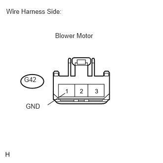
3.CHECK WIRE HARNESS (BLOWER MOTOR - BODY GROUND)
U189805E01
0.507,1.596 0.809,1.777 0.302,0.181 10 G42 0.131,0.152 1.520,0.483 1.389,0.331 10 Wire Harness Side: 1.373,1.965 1.004,2.213 false 0.542,2.16 0.885,2.326 0.343,0.165 10 GND 1.162,0.666 2.124,1.012 0.963,0.346 10 Blower Motor

a.

Disconnect the G42 motor connector.


b.

Measure the resistance of the wire harness side connector.

Standard resistance:
Tester Connection Specified Condition
G42-1 (GND) - Body ground Below 1 Ω


OK

4.CHECK WIRE HARNESS (BLOWER MOTOR - BATTERY)

NG

REPAIR OR REPLACE HARNESS OR CONNECTOR

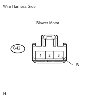
4.CHECK WIRE HARNESS (BLOWER MOTOR - BATTERY)
U189806E01
0.449,1.58 0.740,1.761 0.291,0.181 10 G42 0.105,0.135 1.604,0.464 1.499,0.329 10 Wire Harness Side: 2.114,1.962 2.523,2.252 false 2.566,2.171 2.776,2.332 0.210,0.161 10 +B 1.258,0.712 2.143,1.049 0.885,0.338 10 Blower Motor

a.

Disconnect the G42 motor connector.


b.

Measure the voltage of the wire harness side connector.

Standard voltage:
Tester Connection Condition Specified Condition
G42-3 (+B) - Body ground Ignition switch on (IG) 10 to 14 V


OK

5.CHECK BLOWER W/ FAN MOTOR SUB-ASSEMBLY

NG

REPAIR OR REPLACE HARNESS OR CONNECTOR

5.CHECK BLOWER W/ FAN MOTOR SUB-ASSEMBLY
a.

Disconnect the G47 amplifier connector.
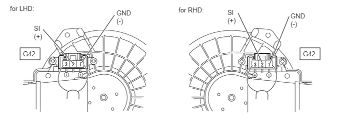
E358380E01
0.417,1 0.833,1.25 0.417,0.25 6.25,1 6.667,1.25 0.417,0.25 1.698,1.313 2.385,0.313 true 1.521,1.323 0.896,0.615 true 5.625,1.323 6.021,0.344 true 5.458,1.302 4.958,0.271 true 0.208,0.094 0.927,0.354 0.719,0.26 10 false for LHD: 0.708,0.51 0.906,0.917 0.198,0.406 10 false SI (+) 2.427,0.188 2.792,0.615 0.365,0.427 10 false GND (-) 3.719,0.125 4.354,0.385 0.635,0.26 10 false for RHD: 0.479,1.042 0.844,1.271 0.365,0.229 10 false G42 6.313,1.042 6.677,1.271 0.365,0.229 10 false G42 4.74,0.177 4.938,0.573 0.198,0.396 10 false SI (+) 6.052,0.25 6.417,0.677 0.365,0.427 10 false GND (-)


b.

Connect the G42 motor connector.


c.

Measure the voltage of the connector.

Standard voltage:
Tester Connection Condition Specified Condition
G42-2 (SI) - G42-1 (GND) Ignition switch on (IG) 4.5 to 5.5 V


OK

6.CHECK WIRE HARNESS (AIR CONDITIONING AMPLIFIER - BODY GROUND)

NG

REPLACE BLOWER W/ FAN MOTOR SUB-ASSEMBLY

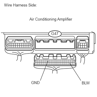
6.CHECK WIRE HARNESS (AIR CONDITIONING AMPLIFIER - BODY GROUND)
U189846E02
2.469,2.24 2.865,2.854 false 1.698,2.156 1.427,2.854 false 0.146,0.094 1.427,0.281 1.281,0.188 10 false Wire Harness Side: 1.042,0.594 2.615,0.771 1.573,0.177 10 false Air Conditioning Amplifier 2.896,2.854 3.219,3.031 0.323,0.177 10 false BLW 1.813,1.104 2.094,1.281 0.281,0.177 10 false G47 1.104,2.844 1.469,3.021 0.365,0.177 10 false GND

a.

Disconnect the G47 amplifier connector.


b.

Measure the voltage of the wire harness side connector.

Standard voltage:
Tester Connection Condition Specified Condition
G47-23 (BLW) - G47-14 (GND) Ignition switch on (IG)
Blower switch OFF
4.5 to 5.5 V


OK

7.CHECK AIR CONDITIONING AMPLIFIER

NG

REPAIR OR REPLACE HARNESS OR CONNECTOR

7.CHECK AIR CONDITIONING AMPLIFIER
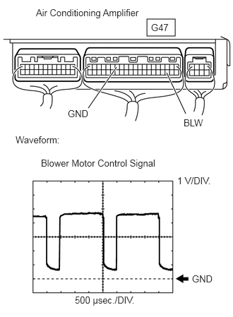
E358388E01
2.167,0.281 2.583,0.531 0.417,0.25 1.302,1.594 1.719,0.99 true 2.74,1.677 2.458,1.073 true 0.531,0.104 2.469,0.344 1.938,0.24 10 false Air Conditioning Amplifier 2.229,0.323 2.667,0.552 0.438,0.229 10 false G47 1,1.594 1.438,1.823 0.438,0.229 10 false GND 2.708,1.729 3.146,1.958 0.438,0.229 10 false BLW 0.229,1.979 1.073,2.229 0.844,0.25 10 false Waveform: 0.604,2.323 2.552,2.646 1.948,0.323 10 false Blower Motor Control Signal 2.615,2.583 3.26,2.844 0.646,0.26 10 false 1 V/DIV. 2.833,4.031 3.271,4.26 0.438,0.229 10 false GND 1.104,4.344 2.417,4.615 1.313,0.271 10 false 500 μsec./DIV.

a.

Remove the air conditioning amplifier with its connectors still connected.


b.

Check the waveform of the amplifier connector.

OK:

Waveform is as shown in the illustration.


HINT:

The waveform varies with the blower level.


Item Content
Tester Connection BLW (G47-23) - GND (G47-14)
Tool Setting 1 V/DIV., 500 μsec./DIV.
Condition Ignition switch on (IG)
Blower switch LO


OK

REPLACE BLOWER W/ FAN MOTOR SUB-ASSEMBLY

NG

REPLACE AIR CONDITIONING AMPLIFIER