Home › Vehicle Interior › AIR CONDITIONING › AIR CONDITIONING SYSTEM
RM24M0E _58 Vehicle Interior _059584 AIR CONDITIONING _0292180 AIR CONDITIONING SYSTEM J

AIR CONDITIONING  AIR CONDITIONING SYSTEM  Rear Air Conditioning Relay Circuit  


DESCRIPTION

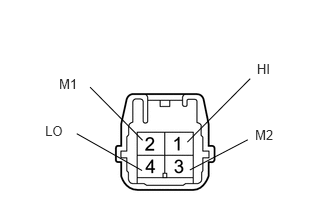
When the rear cooler control (rear blower switch) is set to position LO or higher, the contact of the rear cooler relay is closed, current flows to the rear blower motor, and the rear blower motor operates. The rear blower motor speed can be changed by exchanging the ground and the rear blower resistor circuit with the rear cooler control (rear blower switch).

WIRING DIAGRAM
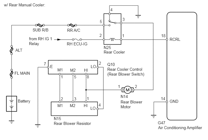
E127606E02
5.438,4.146 7.052,4.563 1.615,0.417 10 false G47 5.844,1.271 6.25,1.448 0.406,0.177 10 false RCRL 5.844,3.406 6.25,3.583 0.406,0.177 10 false GND 3.573,1.552 4.396,1.896 0.823,0.344 10 false N25 1.854,4 3.25,4.438 1.396,0.438 10 false N15 4.156,3.24 4.99,3.781 0.833,0.542 10 false N14 3.698,2.135 4.219,2.385 0.521,0.25 10 false Q10 1.125,0.948 1.771,1.125 0.646,0.177 10 false SUB R/B 0.135,0.083 2.313,0.26 2.177,0.177 10 false w/ Rear Manual Cooler: 2.313,0.958 2.875,1.135 0.563,0.177 10 false RR A/C 0.5,2.438 1.094,2.74 0.594,0.302 10 false FL MAIN 0.531,1.646 0.854,1.896 0.323,0.25 10 false ALT 2.302,1.427 3.104,1.604 0.802,0.177 10 false RH ECU-IG 1,1.25 1.813,1.594 0.813,0.344 10 false from RH IG 1 Relay 3.125,2.208 3.323,2.385 0.198,0.177 10 false LO 3.115,3.646 3.313,3.823 0.198,0.177 10 false LO 2.896,2.333 3.094,2.51 0.198,0.177 10 false HI 2.417,2.333 2.656,2.51 0.24,0.177 10 false M2 1.979,2.323 2.208,2.5 0.229,0.177 10 false M1 2.885,3.552 3.083,3.729 0.198,0.177 10 false HI 2.406,3.552 2.646,3.729 0.24,0.177 10 false M2 1.979,3.552 2.208,3.729 0.229,0.177 10 false M1 1.729,2.208 1.875,2.385 0.146,0.177 10 false E 5.552,1.146 5.719,1.323 0.167,0.177 10 false 18 5.542,3.313 5.708,3.49 0.167,0.177 10 false 14 4.063,2.896 4.219,3.073 0.156,0.177 10 false 1 4.208,1.146 4.365,1.323 0.156,0.177 10 false 1 2.094,3.323 2.25,3.5 0.156,0.177 10 false 2 2.552,3.323 2.708,3.5 0.156,0.177 10 false 3 4.219,0.583 4.375,0.76 0.156,0.177 10 false 3 2.99,3.313 3.146,3.49 0.156,0.177 10 false 1 2.094,2.563 2.25,2.74 0.156,0.177 10 false 1 2.552,2.563 2.708,2.74 0.156,0.177 10 false 5 3.438,0.656 3.594,0.833 0.156,0.177 10 false 5 2.99,2.563 3.146,2.74 0.156,0.177 10 false 8 3.406,2.094 3.563,2.271 0.156,0.177 10 false 2 1.51,2.115 1.667,2.292 0.156,0.177 10 false 7 3.396,3.531 3.552,3.708 0.156,0.177 10 false 4 3.802,0.25 3.958,0.427 0.156,0.177 10 false 4 4.646,2.896 4.802,3.073 0.156,0.177 10 false 2 3.427,1.135 3.583,1.313 0.156,0.177 10 false 2 0.615,3.396 1.073,3.573 0.458,0.177 10 false Battery 3.573,1.708 4.396,2.052 0.823,0.344 10 false Rear Cooler 1.854,4.167 3.25,4.604 1.396,0.438 10 false Rear Blower Resistor 5.448,4.313 7.063,4.729 1.615,0.417 10 false Air Conditioning Amplifier 4.156,3.427 4.938,3.927 0.781,0.5 10 false Rear Blower Motor 3.698,2.302 5.01,2.854 1.313,0.552 10 false Rear Cooler Control (Rear Blower Switch)

PROCEDURE

1.INSPECT FUSE (RR A/C, RH ECU-IG)
a.

Remove the RR A/C H-fuse from the main body ECU.


b.

Remove the RH ECU-IG fuse from the instrument junction block RH.


c.

Measure the resistance of the fuses.

Standard resistance:

Below 1 Ω


OK

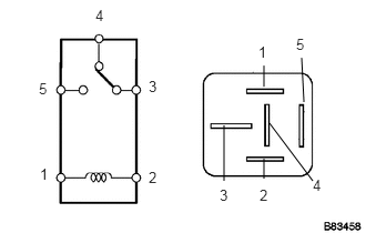
2.INSPECT REAR COOLER RELAY

NG

REPLACE FUSE

2.INSPECT REAR COOLER RELAY
B083458E08
2.104,1.698 2.104,1.177 false 2.479,1.677 2.479,1.49 false 2.479,0.615 2.479,0.813 false 2.833,0.542 2.854,0.958 false 2.938,1.698 2.531,1.156 false 2.781,0.333 2.927,0.521 0.146,0.188 10 false 5 2.427,0.406 2.573,0.594 0.146,0.188 10 false 1 2.938,1.656 3.083,1.844 0.146,0.188 10 false 4 1.396,0.729 1.542,0.917 0.146,0.188 10 false 3 2.438,1.75 2.583,1.938 0.146,0.188 10 false 2 0.365,0.75 0.51,0.938 0.146,0.188 10 false 5 0.375,1.552 0.521,1.74 0.146,0.188 10 false 1 0.896,0.063 1.042,0.25 0.146,0.188 10 false 4 2.063,1.75 2.208,1.938 0.146,0.188 10 false 3 1.396,1.583 1.542,1.771 0.146,0.188 10 false 2

a.

Remove the rear cooler relay.


b.

Measure the resistance of the relay.

Standard resistance:
Tester Connection Specified Condition
3 - 4 Below 1 Ω
3 - 5 10 kΩ or higher
3 - 4 10 kΩ or higher
(when battery voltage is applied to terminals 1 and 2)
3 - 5 Below 1 Ω
(when battery voltage is applied to terminals 1 and 2)


OK

3.INSPECT REAR BLOWER MOTOR

NG

REPLACE REAR COOLER RELAY

3.INSPECT REAR BLOWER MOTOR
U189860E02
1.76,1.115 2.49,0.49 true 1.635,1.104 0.948,0.396 true 0.813,0.292 0.969,0.469 0.156,0.177 10 false 2 2.542,0.344 2.698,0.521 0.156,0.177 10 false 1 1.563,0.177 1.833,0.354 0.271,0.177 10 false N14

a.

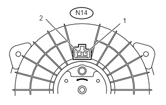
Disconnect the N14 motor connector.


b.

Connect the battery's positive (+) lead to terminal 2 and the negative (-) lead to terminal 1, then check that the rear blower motor operates smoothly.

OK:

The rear blower motor operates smoothly.


c.

Measure the current of the connector.

Standard current:
Tester Connection Condition Specified Condition
N14-1 - N14-2 Rear blower motor operates 1 to 3 A


OK

4.INSPECT REAR COOLER CONTROL (REAR BLOWER SWITCH)

NG

REPLACE REAR BLOWER MOTOR

4.INSPECT REAR COOLER CONTROL (REAR BLOWER SWITCH)
E127608E03
1.896,2 2.552,1.458 false 2.073,2.031 2.594,1.76 false 1.01,2.625 1.417,2.292 false 2.094,2.292 2.573,2.51 false 1.708,2.281 1.99,2.646 false 0.813,0.479 2.135,0.823 1.323,0.344 10 false Rear Cooler Control (Rear Blower Switch) 2.635,1.333 2.833,1.51 0.198,0.177 10 false LO 2.667,1.656 2.875,1.833 0.208,0.177 10 false M1 2.625,2.469 2.896,2.667 0.271,0.198 10 false M2 2,2.656 2.156,2.833 0.156,0.177 10 false E 0.854,2.594 1.01,2.771 0.156,0.177 10 false HI

a.

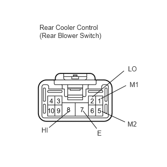
Remove the rear cooler control.


b.

Measure the resistance of the switch.

Standard resistance:
Tester Connection Switch Position Specified Condition
ALL - 7 (E) OFF 10 kΩ or higher
2 (LO) - 7 (E) LO Below 1 Ω
2 (LO) - 7 (E) - 1 (M1) LO to M1 Below 1 Ω
2 (LO) - 7 (E) - 1 (M1) M1 Below 1 Ω
2 (LO) - 7 (E) - 1 (M1) - 5 (M2) M1 to M2 Below 1 Ω
2 (LO) - 7 (E) - 5 (M2) M2 Below 1 Ω
2 (LO) - 7 (E) - 5 (M2) - 8(HI) M2 to HI Below 1 Ω
2 (LO) - 7 (E) - 8 (HI) HI Below 1 Ω


OK

5.INSPECT REAR BLOWER RESISTOR

NG

REPLACE REAR COOLER CONTROL

5.INSPECT REAR BLOWER RESISTOR
E120977E05
1.951,1.48 2.606,0.819 false 1.485,1.461 0.938,0.907 false 1.479,1.776 0.799,1.392 false 1.977,1.77 2.581,1.455 false 2.676,0.64 2.867,0.813 0.191,0.173 10 HI 2.657,1.326 2.938,1.497 0.281,0.171 10 M2 0.615,0.79 0.870,0.982 0.256,0.192 10 M1 0.47,1.28 0.703,1.471 0.233,0.191 10 LO

a.

Remove the rear blower resistor.


b.

Measure the resistance of the resistor.

Standard resistance:
Tester Connection Specified Condition
N15-1 (HI) - N15-2 (M1) 1.32 to 1.52 Ω
N15-1 (HI) - N15-3 (M2) 0.39 to 0.45Ω
N15-1 (HI) - N15-4 (LO) 2.08 to 2.40 Ω


OK

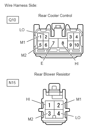
6.CHECK WIRE HARNESS (REAR COOLER CONTROL - REAR BLOWER RESISTOR)

NG

REPLACE REAR BLOWER RESISTOR

6.CHECK WIRE HARNESS (REAR COOLER CONTROL - REAR BLOWER RESISTOR)
E358395E01
0.25,0.583 0.667,0.833 0.417,0.25 0.25,2.833 0.667,3.083 0.417,0.25 1.01,1.917 1.417,1.646 true 0.958,1.49 1.396,1.302 true 1.594,1.229 0.948,1.094 true 1.552,2.156 1.885,1.583 true 2.698,2.156 2.229,1.583 true 2.188,3.74 2.667,3.563 true 2.188,4.052 2.635,4.156 true 1.135,3.573 1.646,3.75 true 1.271,4.219 1.698,4.052 true 0.167,0.104 1.469,0.417 1.302,0.313 10 false Wire Harness Side: 1.375,0.469 2.813,0.75 1.438,0.281 10 false Rear Cooler Control 0.313,0.625 0.76,0.833 0.448,0.208 10 false Q10 0.698,0.979 1.146,1.188 0.448,0.208 10 false LO 0.719,1.427 1.167,1.635 0.448,0.208 10 false M1 0.76,1.885 1.208,2.094 0.448,0.208 10 false M2 1.458,2.177 1.906,2.385 0.448,0.208 10 false E 2.677,2.188 3.125,2.396 0.448,0.208 10 false HI 1.229,2.563 2.75,2.865 1.521,0.302 10 false Rear Blower Resistor 0.313,2.865 0.76,3.073 0.448,0.208 10 false N15 0.938,3.458 1.385,3.667 0.448,0.208 10 false HI 1,4.167 1.448,4.375 0.448,0.208 10 false M2 2.729,3.458 3.177,3.667 0.448,0.208 10 false M1 2.698,4.115 3.146,4.323 0.448,0.208 10 false LO

a.

Disconnect the Q10 rear cooler control connector.


b.

Disconnect the N15 rear blower resistor connector.


c.

Measure the resistance of the wire harness side connectors.

Standard resistance:
Tester Connection Specified Condition
Q10-1 (M1) - N15-2 (M1) Below 1 Ω
Q10-5 (M2) - N15-3 (M2) Below 1 Ω
Q10-8 (HI) - N15-1 (HI) Below 1 Ω
Q10-2 (LO) - N15-4 (LO) Below 1 Ω
Q10-7 (E) - Body ground Below 1 Ω


OK

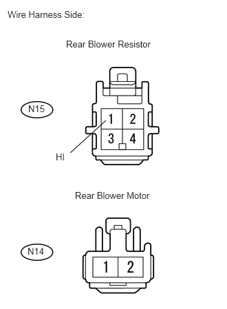
7.CHECK WIRE HARNESS (REAR BLOWER RESISTOR - REAR BLOWER MOTOR)

NG

REPAIR OR REPLACE HARNESS OR CONNECTOR

7.CHECK WIRE HARNESS (REAR BLOWER RESISTOR - REAR BLOWER MOTOR)
U189864E02
1.604,1.823 1.063,2.313 false 0.115,0.135 1.396,0.323 1.281,0.188 10 false Wire Harness Side: 1,0.583 2.385,0.76 1.385,0.177 10 false Rear Blower Resistor 1.135,2.875 2.313,3.052 1.177,0.177 10 false Rear Blower Motor 0.844,2.292 1,2.469 0.156,0.177 10 false HI 0.427,1.563 0.698,1.74 0.271,0.177 10 false N15 0.417,3.719 0.688,3.896 0.271,0.177 10 false N14

a.

Disconnect the N15 rear blower resistor connector.


b.

Disconnect the N14 rear motor connector.


c.

Measure the resistance of the wire harness side connectors.

Standard resistance:
Tester Connection Specified Condition
N15-1 (HI) - N14-1 Below 1 Ω


OK

8.CHECK WIRE HARNESS (REAR BLOWER MOTOR - BODY GROUND AND BATTERY)

NG

REPAIR OR REPLACE HARNESS OR CONNECTOR

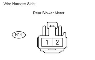
8.CHECK WIRE HARNESS (REAR BLOWER MOTOR - BODY GROUND AND BATTERY)
U189865E02
0.125,0.052 1.406,0.24 1.281,0.188 10 false Wire Harness Side: 1.198,0.385 2.375,0.563 1.177,0.177 10 false Rear Blower Motor 0.542,1.167 0.813,1.344 0.271,0.177 10 false N14

a.

Disconnect the N14 rear motor connector.


b.

Measure the resistance of the wire harness side connector.

Standard resistance:
Tester Connection Specified Condition
N14-2 - Body ground Below 1 Ω


c.

Measure the voltage of the wire harness side connector.

Standard voltage:
Tester Connection Condition Specified Condition
N14-2 - Body ground Ignition switch on (IG)
Heater control (blower switch) 1
10 to 14 V


OK

9.CHECK WIRE HARNESS (AIR CONDITIONING AMPLIFIER - BATTERY)

NG

REPAIR OR REPLACE HARNESS OR CONNECTOR

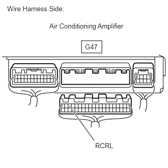
9.CHECK WIRE HARNESS (AIR CONDITIONING AMPLIFIER - BATTERY)
E358387E01
1.667,0.833 2.083,1.083 0.417,0.25 1.927,2.875 1.417,2.167 true 0.146,0.094 1.917,0.448 1.771,0.354 10 false Wire Harness Side: 1.01,0.448 2.698,0.76 1.688,0.313 10 false Air Conditioning Amplifier 1.74,0.875 2.302,1.167 0.563,0.292 10 false G47 1.948,2.896 2.51,3.188 0.563,0.292 10 false RCRL

a.

Disconnect the G47 amplifier connector.


b.

Measure the voltage of the wire harness side connector.

Standard voltage:
Tester Connection Condition Specified Condition
G47-18 (RCRL) - Body ground Ignition switch on (IG)
Heater control (blower switch): OFF
10 to 14 V
G47-18 (RCRL) - Body ground Ignition switch on (IG)
Heater control (blower switch): ON
Below 1 V


OK

10.CHECK WIRE HARNESS (AIR CONDITIONING AMPLIFIER - BODY GROUND)

NG

REPAIR OR REPLACE HARNESS OR CONNECTOR

10.CHECK WIRE HARNESS (AIR CONDITIONING AMPLIFIER - BODY GROUND)
U189849E02
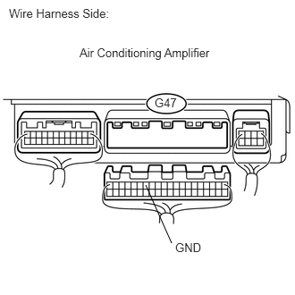
1.698,2.156 2,2.833 false 0.104,0.073 1.385,0.26 1.281,0.188 10 false Wire Harness Side: 0.927,0.531 2.5,0.708 1.573,0.177 10 false Air Conditioning Amplifier 2.042,2.802 2.365,2.979 0.323,0.177 10 false GND 1.802,1.115 2.083,1.292 0.281,0.177 10 false G47

a.

Disconnect the G47 amplifier connector.


b.

Measure the resistance of the wire harness side connector.

Standard resistance:
Tester Connection Specified Condition
G47-14 (GND) - Body ground Below 1 Ω


OK

PROCEED TO NEXT CIRCUIT INSPECTION SHOWN IN PROBLEM SYMPTOMS TABLE

NG

REPAIR OR REPLACE HARNESS OR CONNECTOR