Home › Vehicle Interior › AIR CONDITIONING › AIR CONDITIONING SYSTEM
RM24M0E _58 Vehicle Interior _059584 AIR CONDITIONING _0292180 AIR CONDITIONING SYSTEM C

AIR CONDITIONING  AIR CONDITIONING SYSTEM  B1447/47  Rear Air Mix Damper Control Servo Motor Circuit  


DESCRIPTION

The rear air mix damper servo sends pulse signals to indicate the damper position to the air conditioning amplifier. The air conditioning amplifier activates the motor (normal or reverse) based on these signals to move the rear air mix damper to the appropriate position. This adjusts the amount of air passing through the heater core after passing the evaporator and controls the temperature of the blown air.

HINT:

Confirm that there are no mechanical problems because this DTC can be output when either a damper link or damper is mechanically locked.


DTC No. DTC Detection Condition Trouble Area
B1447/47 Rear air mix damper position does not change even if air conditioning amplifier operates rear air mix damper control servo motor
·

Rear air mix control servo motor

·

Rear air conditioning harness

·

Wire harness between rear air conditioning harness and air conditioning amplifier

·

Air conditioning amplifier


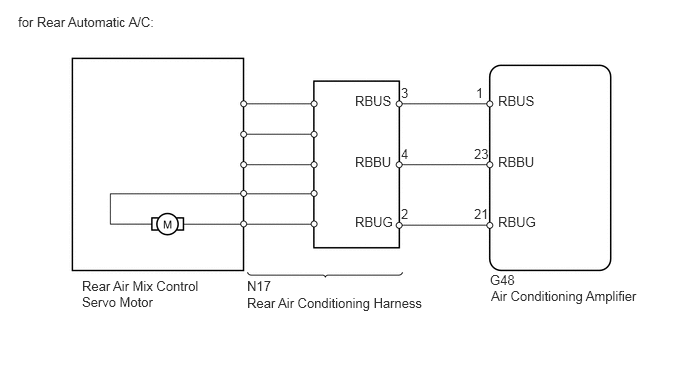
WIRING DIAGRAM

E127600E45
5.104,2.833 6.677,3.177 1.573,0.344 10 false G48 2.573,2.896 4.469,3.24 1.896,0.344 10 false N17 0.854,2.896 2.156,3.24 1.302,0.344 10 false Rear Air Mix Control Servo Motor 5.188,0.969 5.594,1.146 0.406,0.177 10 false RBUS 3.698,0.969 4.104,1.146 0.406,0.177 10 false RBUS 0.188,0.146 1.781,0.333 1.594,0.188 10 false for Rear Automatic A/C: 4.958,0.885 5.115,1.063 0.156,0.177 10 false 1 4.177,0.885 4.333,1.063 0.156,0.177 10 false 3 5.188,1.604 5.594,1.781 0.406,0.177 10 false RBBU 3.698,1.604 4.104,1.781 0.406,0.177 10 false RBBU 4.938,1.521 5.104,1.698 0.167,0.177 10 false 23 4.177,1.521 4.333,1.698 0.156,0.177 10 false 4 5.188,2.229 5.604,2.406 0.417,0.177 10 false RBUG 3.698,2.229 4.115,2.406 0.417,0.177 10 false RBUG 4.938,2.146 5.104,2.323 0.167,0.177 10 false 21 4.177,2.146 4.333,2.323 0.156,0.177 10 false 2 2.573,3.073 4.469,3.417 1.896,0.344 10 false Rear Air Conditioning Harness 5.115,3 6.688,3.344 1.573,0.344 10 false Air Conditioning Amplifier

PROCEDURE

1.READ VALUE USING INTELLIGENT TESTER (AIR MIX PULSE-R)
a.

Connect the intelligent tester to the DLC3.


b.

Turn the ignition switch on (IG) and turn the intelligent tester main switch ON.


c.

Select the items below in the Data List, and read the value displayed on the intelligent tester.

Air conditioning amplifier:
Item Measurement Item / Display (Range) Normal Condition Diagnostic Note
Air Mix Pulse-R Rear air mix servo motor target pulse /
Min.: 0, Max.: 255
Customized value displayed -


OK:

The display is as specified in the normal condition column.


Result
Result Proceed to
NG A
OK (Checking from PROBLEM SYMPTOMS TABLE) B
OK (Checking from DTC) C


A

2.CHECK WIRE HARNESS (REAR AIR CONDITIONING HARNESS - AIR CONDITIONING AMPLIFIER)

B

PROCEED TO NEXT CIRCUIT INSPECTION SHOWN IN PROBLEM SYMPTOMS TABLE

C

REPLACE AIR CONDITIONING AMPLIFIER

2.CHECK WIRE HARNESS (REAR AIR CONDITIONING HARNESS - AIR CONDITIONING AMPLIFIER)
a.

Disconnect the N17 rear air conditioning harness connector.
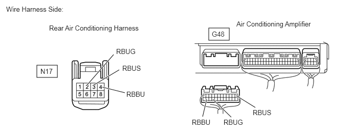
E358391E02
0.75,1.333 1.167,1.583 0.417,0.25 4.25,0.573 4.667,0.823 0.417,0.25 2.083,1.781 2.542,1.896 true 1.906,1.74 2.427,1.427 true 4.125,2.385 4.208,2.031 true 5.198,2.198 4.813,1.958 true 1.771,1.74 2.313,1.115 true 4.708,2.396 4.333,2.031 true 0.125,0.104 1.635,0.531 1.51,0.427 10 false Wire Harness Side: 1,0.49 3.24,0.958 2.24,0.469 10 false Rear Air Conditioning Harness 0.823,1.375 1.365,1.656 0.542,0.281 10 false N17 2.49,1.313 3.031,1.594 0.542,0.281 10 false RBUS 2.573,1.844 3.115,2.125 0.542,0.281 10 false RBBU 4.313,0.615 4.854,0.896 0.542,0.281 10 false G48 4.813,0.406 6.448,0.708 1.635,0.302 10 false Air Conditioning Amplifier 2.365,0.969 2.906,1.25 0.542,0.281 10 false RBUG 3.906,2.417 4.448,2.698 0.542,0.281 10 false RBBU 4.552,2.417 5.094,2.698 0.542,0.281 10 false RBUG 5.146,2.219 5.688,2.5 0.542,0.281 10 false RBUS


b.

Disconnect the G48 amplifier connector.


c.

Measure the resistance of the wire harness side connectors.

Standard resistance:
Tester Connection Specified Condition
N17-3 (RBUS) - G48-1 (RBUS) Below 1 Ω
N17-4 (RBBU) - G48-23 (RBBU) Below 1 Ω
N17-2 (RBUG) - G48-21 (RBUG) Below 1 Ω
G48-1 (RBUS) - Body ground 10 kΩ or higher
G48-23 (RBBU) - Body ground 10 kΩ or higher
G48-21 (RBUG) - Body ground 10 kΩ or higher


OK

3.REPLACE REAR AIR MIX CONTROL SERVO MOTOR

NG

REPAIR OR REPLACE HARNESS OR CONNECTOR

3.REPLACE REAR AIR MIX CONTROL SERVO MOTOR
HINT:

Since the servo motor cannot be tested when it is removed from the vehicle, replace the servo motor with a normal one and check that the condition returns to normal.


OK:

Same problem does not occur.


OK

SYSTEM IS OK

NG

REPAIR OR REPLACE REAR AIR CONDITIONING HARNESS