RM24M0E
_58
Vehicle Interior
_059585
THEFT DETERRENT
_0292193
THEFT DETERRENT SYSTEM
J
THEFT DETERRENT THEFT DETERRENT SYSTEM ECU Power Source Circuit
DESCRIPTION
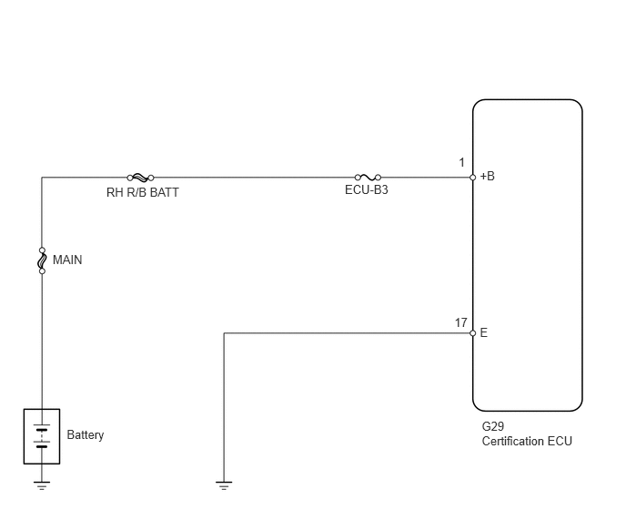
This circuit provides power to operate the certification ECU.
WIRING DIAGRAM
1.218,2.117 2.106,2.342
0.888,0.225
10
RH R/B BATT
3.948,2.086 4.553,2.297
0.605,0.211
10
ECU-B3
0.603,2.885 0.995,3.069
0.392,0.184
10
MAIN
0.764,4.882 1.281,5.065
0.517,0.184
10
Battery
5.494,1.93 5.736,2.086
0.242,0.156
10
+B
5.494,3.716 5.872,3.969
0.378,0.253
10
E
5.515,4.957 6.627,5.125
1.112,0.167
10
Certification ECU
5.249,1.768 5.398,1.963
0.149,0.196
10
1
5.202,3.604 5.393,3.800
0.191,0.196
10
17
5.515,4.79 5.810,4.932
0.295,0.142
10
G29
PROCEDURE
1.INSPECT FUSE (ECU-B3)
a.
Remove the ECU-B3 fuse from the engine room No. 2 relay block.
b.
Measure the resistance of the fuse.
- Standard resistance:
Below 1 Ω
OK
2.CHECK WIRE HARNESS (CERTIFICATION ECU - BATTERY AND BODY GROUND)
NG
REPLACE FUSE
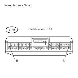
2.CHECK WIRE HARNESS (CERTIFICATION ECU - BATTERY AND BODY GROUND)
0.635,2.583 0.406,2.01
false
2.854,2.563 3.042,2.01
false
0.198,0.146 1.698,0.354
1.5,0.208
10
false
Wire Harness Side:
2.771,2.573 2.927,2.781
0.156,0.208
10
false
E
0.625,2.594 0.833,2.76
0.208,0.167
10
false
+B
0.396,1.229 0.75,1.427
0.354,0.198
10
false
G29
1.25,1.198 2.354,1.365
1.104,0.167
10
false
Certification ECU
a.
Disconnect the G29 ECU connector.
b.
Measure the resistance of the wire harness side connector.
- Standard resistance:
Tester Connection Specified Condition G29-17 (E) - Body ground Below 1 Ω
c.
Measure the voltage of the wire harness side connector.
- Standard voltage:
Tester Connection Specified Condition G29-1(+B) - Body ground 10 to 14 V
OK
REPLACE CERTIFICATION ECU
NG
REPAIR OR REPLACE HARNESS OR CONNECTOR