Home › Vehicle Interior › THEFT DETERRENT › THEFT DETERRENT SYSTEM
RM24M0E _58 Vehicle Interior _059585 THEFT DETERRENT _0292193 THEFT DETERRENT SYSTEM J

THEFT DETERRENT  THEFT DETERRENT SYSTEM  Security Indicator Light Circuit  


DESCRIPTION

When the theft deterrent system is in the disarmed state, the security indicator will flash continuously if the immobiliser system is set, or not illuminate if the immobiliser system is not set.

When the theft deterrent system is in the armed state, the immobiliser system is automatically set and the security indicator will flash continuously.

When the theft deterrent system is in the arming preparation state and alarm sounding state, the certification ECU causes the security indicator to be illuminated.


WIRING DIAGRAM
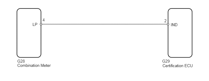
B144220E10
5.573,2.188 6.719,2.375 1.146,0.188 10 false Certification ECU 5.635,0.635 5.76,0.833 0.125,0.198 10 false 2 1.458,0.604 1.667,0.802 0.208,0.198 10 false 4 1.115,0.76 1.427,0.969 0.313,0.208 10 false LP 0.594,2.177 2.031,2.385 1.438,0.208 10 false Combination Meter 0.594,2.031 0.906,2.26 0.313,0.229 10 false G28 5.563,2.031 5.854,2.188 0.292,0.156 10 false G29 5.854,0.771 6.167,1.021 0.313,0.25 10 false IND

PROCEDURE

1.PERFORM ACTIVE TEST USING INTELLIGENT TESTER (SECURITY INDICATOR)
a.

Select the Active Test, use the intelligent tester to generate a control command, and then check that the indicator illuminates.

Certification ECU:
Item Test Details Diagnostic Note
SECURITY INDIC Security indicator ON / OFF -

OK:

Security indicator illuminates.


NG

2.CHECK WIRE HARNESS (COMBINATION METER - CERTIFICATION ECU)

OK

REPLACE CERTIFICATION ECU

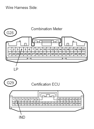
2.CHECK WIRE HARNESS (COMBINATION METER - CERTIFICATION ECU)
U185939E03
0.781,1.813 0.583,2.396 false 0.615,3.625 0.781,4.156 false 0.208,0.188 1.927,0.354 1.719,0.167 10 false Wire Harness Side: 1.135,0.958 2.354,1.125 1.219,0.167 10 false Combination Meter 0.24,1.104 0.563,1.25 0.323,0.146 10 false G28 0.25,2.917 0.573,3.063 0.323,0.146 10 false G29 1.146,2.969 2.271,3.125 1.125,0.156 10 false Certification ECU 0.5,2.427 0.729,2.594 0.229,0.167 10 false LP 0.688,4.167 0.969,4.313 0.281,0.146 10 false IND

a.

Disconnect the G28 meter connector.


b.

Disconnect the G29 ECU connector.


c.

Measure the resistance of the wire harness side connectors.

Standard resistance:
Tester Connection Specified Condition
G28-4 (LP) - G29-2 (IND) Below 1 Ω
G28-4 (LP) - Body ground 10 kΩ or higher


OK

3.CHECK OPERATION OF COMBINATION METER

NG

REPAIR OR REPLACE HARNESS AND CONNECTOR

3.CHECK OPERATION OF COMBINATION METER
a.

Temporarily replace the combination meter with a new or normally functioning combination meter.


b.

Check the security indicator operation.

OK:

Security indicator operates normally.


OK

END (COMBINATION METER IS FAULTY)

NG

REPLACE CERTIFICATION ECU