METER / GAUGE / DISPLAY METER / GAUGE SYSTEM TERMINALS OF ECU
w/o Multi-information Display
Combination Meter Sub-assembly

Disconnect the G28 combination meter sub-assembly connector.
Measure the voltage and resistance according to the value(s) in the table below.
| Symbols (Terminal No.) | Wiring Color | Terminal Description | Condition | Specified Condition |
|---|---|---|---|---|
| ES (G28-20) - Body ground* | W-B - Body ground | Ground (Tire pressure warning ECU and receiver ground) | Always | Below 1 Ω |
| IG2 (G28-21) - Body ground | G - Body ground | Ignition power supply | Engine switch off | Below 1 V |
| IG2 (G28-21) - Body ground | G - Body ground | Ignition power supply | Engine switch on (IG) | 10 to 14 V |
| B (G28-22) - Body ground | W - Body ground | Battery power supply | Always | 10 to 14 V |
| EP (G28-33) - Body ground | BR - Body ground | Ground (Meter ground) | Always | Below 1 Ω |
- HINT:
-
*: w/ Tire Pressure Warning System
If the result is not as specified, there may be a malfunction on the wire harness side.
Reconnect the G28 combination meter sub-assembly connector.
Measure the voltage according to the value(s) in the table below.
| Symbols (Terminal No.) | Wiring Color | Terminal Description | Condition | Specified Condition |
|---|---|---|---|---|
| LP (G28-4) - Body ground | V - Body ground | Security indicator signal | Security indicator light OFF | Below 1 V |
| LP (G28-4) - Body ground | V - Body ground | Security indicator signal | Security indicator light blinking | Below 1 V ←→ 10 to 14 V |
| PBLT (G28-6)*2 - Body ground | SB - Body ground | Front passenger seat belt condition output signal | Engine switch on (IG), front passenger seat belt warning light is OFF | 10 to 14 V |
| PBLT (G28-6)*2 - Body ground | SB - Body ground | Front passenger seat belt condition output signal | Engine switch on (IG), front passenger seat belt warning light blinking | Below 1 V ←→ 10 to 14 V |
| RSET (G28-8) - Body ground | W - Body ground | Clock "00" switch signal | Engine switch on (IG), clock "00" switch pushed | Below 1 V |
| RSET (G28-8) - Body ground | W - Body ground | Clock "00" switch signal | Engine switch on (IG), clock "00" switch released | 4 to 6 V |
| M (G28-9) - Body ground | R - Body ground | Clock "M" switch signal | Engine switch on (IG), clock "M" switch pushed | Below 1 V |
| M (G28-9) - Body ground | R - Body ground | Clock "M" switch signal | Engine switch on (IG), clock "M" switch released | 4 to 6 V |
| H (G28-10) - Body ground | L - Body ground | Clock "H" switch signal | Engine switch on (IG), clock "H" switch pushed | Below 1 V |
| H (G28-10) - Body ground | L - Body ground | Clock "H" switch signal | Engine switch on (IG), clock "H" switch released | 4 to 6 V |
| CHG- (G28-13) - Body ground | LG - Body ground | Alternator signal | Engine switch on (IG), charge warning light ON | Below 1 V |
| CHG- (G28-13) - Body ground | LG - Body ground | Alternator signal | Engine switch on (IG), charge warning light OFF | 10 to 14 V |
| FLDS (G28-16) - Body ground*3 | W - Body ground | Fold seat signal | Engine switch on (IG), 3rd seat indicator light ON | Below 1 V |
| FLDS (G28-16) - Body ground*3 | W - Body ground | Fold seat signal | Engine switch on (IG), 3rd seat indicator light OFF | 10 to 14 V |
| MPX+ (G28-18) - Body ground | LG - Body ground | CAN communication line | Engine switch on (IG) | Pulse generation |
| MPX- (G28-19) - Body ground | W - Body ground | CAN communication line | Engine switch on (IG) | Pulse generation |
| B (G28-23) - Body ground | Y - Body ground | RH turn indicator light signal | Engine switch on (IG), RH turn indicator light OFF | Below 1 V |
| B (G28-23) - Body ground | Y - Body ground | RH turn indicator light signal | Engine switch on (IG), RH turn indicator light blinking | Below 1 V ←→ 10 to 14 V |
| B (G28-24) - Body ground | Y - Body ground | LH turn indicator light signal | Engine switch on (IG), LH turn indicator light OFF | Below 1 V |
| B (G28-24) - Body ground | Y - Body ground | LH turn indicator light signal | Engine switch on (IG), LH turn indicator light ON | Below 1 V ←→ 10 to 14 V |
| EFI (G28-25) - Body ground | Y - Body ground | MIL (Check engine warning light) signal | Engine switch on (IG), MIL (Check engine warning light) ON | Below 1.5 V*4 |
| Below 3 V*5 | ||||
| EFI (G28-25) - Body ground | Y - Body ground | MIL (Check engine warning light) signal | Engine switch on (IG), MIL (Check engine warning light) OFF | 10 to 14 V |
| #10 (G28-26) - Body ground | L - Body ground | Brake fluid level signal | Engine switch on (IG), brake fluid level not low | 10 to 14 V |
| #10 (G28-26) - Body ground | L - Body ground | Brake fluid level signal | Engine switch on (IG), brake fluid level low | Below 1 V |
| L (G28-27) - FE (G28-30) | L - BE | Fuel level signal | Engine switch on (IG), fuel level full | Below 1 V |
| L (G28-27) - FE (G28-30) | L - BE | Fuel level signal | Engine switch on (IG), fuel level low (fuel level warning light on) | 4.5 to 9 V |
| P/SB (G28-29)*2 - Body ground | G - Body ground | Front passenger seat belt condition input signal | Engine switch on (IG), front passenger seat belt warning light is OFF | 10 to 14 V |
| P/SB (G28-29)*2 - Body ground | G - Body ground | Front passenger seat belt condition input signal | Engine switch on (IG), front passenger seat belt warning light blinking | Below 1 V |
| CANL (G28-31) - Body ground | W - Body ground | CAN communication line | Engine switch on (IG) | Pulse generation |
| CANH (G28-32) - Body ground | B - Body ground | CAN communication line | Engine switch on (IG) | Pulse generation |
| ODO (G28-34) - Body ground | V - Body ground | ODO/TRIP switch signal | Engine switch on (IG), ODO/TRIP switch pushed | Below 1 V |
| ODO (G28-34) - Body ground | V - Body ground | ODO/TRIP switch signal | Engine switch on (IG), ODO/TRIP switch released | 4 to 6 V |
| TC O (G28-35) - Body ground | P - Body ground | Rheostat switch signal | Engine switch on (IG), rheostat switch pushed | Below 1 V |
| TC O (G28-35) - Body ground | P - Body ground | Rheostat switch signal | Engine switch on (IG), rheostat switch released | 4.5 to 5.5 V |
| TIRE (G28-36) - Body ground*1 | B - Body ground | Tire pressure warning signal | Normal condition:
Engine switch on (IG), tire pressure warning light ON |
0.9 to 3.2 V |
| Abnormal condition:
Engine switch on (IG), tire pressure warning light ON |
Below 3.2V | |||
| TIRE (G28-36) - Body ground*1 | B - Body ground | Tire pressure warning signal | Engine switch on (IG), tire pressure warning light OFF | 3.2 V or higher |
| S (G28-38) - Body ground | GR - Body ground | Engine oil pressure warning signal | Engine switch on (IG), engine oil pressure warning light ON | Below 1 V |
| S (G28-38) - Body ground | GR - Body ground | Engine oil pressure warning signal | Engine switch on (IG), engine oil pressure warning light OFF | 10 to 14 V |
| SI (G28-39) - Body ground | V - Body ground | Speed signal (Input) | Engine switch on (IG), slowly turn wheel | Pulse generation |
| +S (G28-40) - Body ground | W - Body ground | Speed signal (Output) | Engine switch on (IG), slowly turn wheel | Pulse generation |
- HINT:
-
*1: w/ Tire Pressure Warning System
-
*2: w/ Front Passenger Seat Belt Warning
-
*3: w/ Rear Power Seat Control System
-
*4: for 2AZ-FE
-
*5: for 2GR-FE
If the result is not as specified, the combination meter sub-assembly may be malfunctioning.
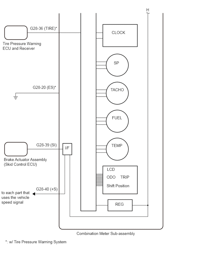
Combination Meter Sub-assembly Inner Circuit
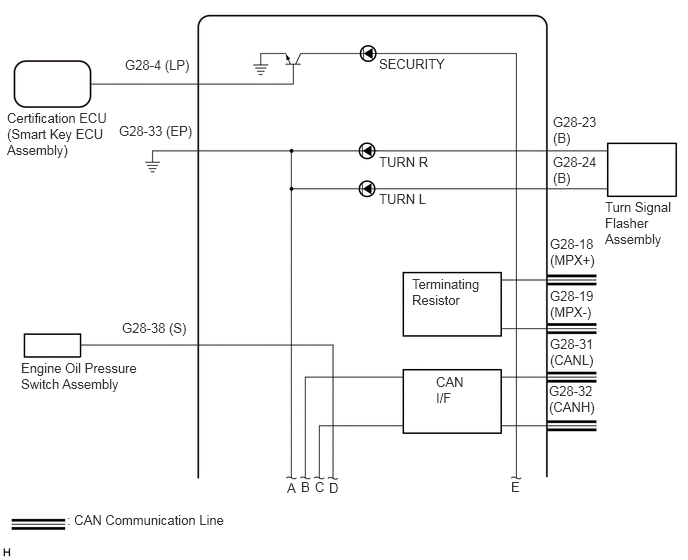
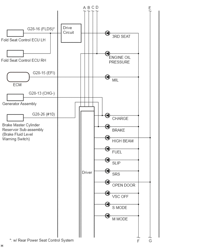
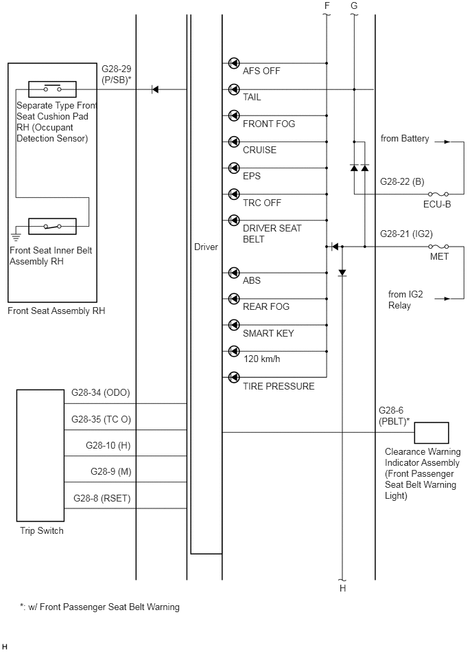
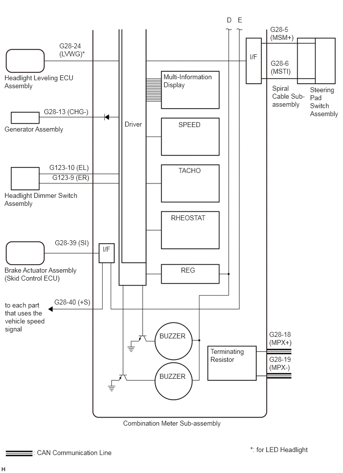
w/ Multi-information Display
Combination Meter Sub-assembly
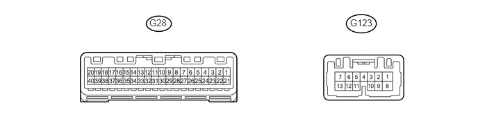
Disconnect the G28 or G123 combination meter sub-assembly connector.
Measure the voltage and resistance according to the value(s) in the table below.
| Symbols (Terminal No.) | Wiring Color | Terminal Description | Condition | Specified Condition |
|---|---|---|---|---|
| IG2 (G28-21) - Body ground | G - Body ground | Ignition power supply | Engine switch off | Below 1 V |
| IG2 (G28-21) - Body ground | G - Body ground | Ignition power supply | Engine switch on (IG) | 10 to 14 V |
| B (G28-22) - Body ground | W - Body ground | Battery power supply | Always | 10 to 14 V |
| EP (G28-33) - Body ground | BR - Body ground | Ground (Meter ground) | Always | Below 1 Ω |
| B (G123-1) - Body ground | P - Body ground | Battery power supply | Always | 10 to 14 V |
If the result is not as specified, there may be a malfunction on the wire harness side.
Reconnect the G28 or G123 combination meter sub-assembly connector.
Measure the voltage according to the value(s) in the table below.
| Symbols (Terminal No.) | Wiring Color | Terminal Description | Condition | Specified Condition |
|---|---|---|---|---|
| MSM+ (G28-5) - Body ground | L - Body ground | Steering pad switch signal | Engine switch on (IG), enter, back and trip switches on steering pad switch assembly not pushed | 4.6 to 5.2 V |
| MSM+ (G28-5) - Body ground | L - Body ground | Steering pad switch signal | Engine switch on (IG), enter switch on steering pad switch assembly pushed | Below 0.8 V |
| MSM+ (G28-5) - Body ground | L - Body ground | Steering pad switch signal | Engine switch on (IG), back switch on steering pad switch assembly pushed | 2.5 to 3.4 V |
| MSM+ (G28-5) - Body ground | L - Body ground | Steering pad switch signal | Engine switch on (IG), trip switch on steering pad switch assembly pushed | 1 to 2.2 V |
| MST1 (G28-6) - Body ground | B - Body ground | Steering pad switch signal | Engine switch on (IG), up, down, right and left switches on steering pad switch assembly not pushed | 4.6 to 5.2 V |
| MST1 (G28-6) - Body ground | B - Body ground | Steering pad switch signal | Engine switch on (IG), up switch on steering pad switch assembly pushed | 1 to 2.2 V |
| MST1 (G28-6) - Body ground | B - Body ground | Steering pad switch signal | Engine switch on (IG), down switch on steering pad switch assembly pushed | 2.5 to 3.4 V |
| MST1 (G28-6) - Body ground | B - Body ground | Steering pad switch signal | Engine switch on (IG), right switch on steering pad switch assembly pushed | 3.7 to 4.4 V |
| MST1 (G28-6) - Body ground | B - Body ground | Steering pad switch signal | Engine switch on (IG), left switch on steering pad switch assembly pushed | Below 0.8 V |
| CHG- (G28-13) - Body ground | LG - Body ground | Generator signal | Engine switch on (IG), "Charging System Malfunction See Owner's Manual" not displayed on multi-information display | 10 to 14 V |
| CHG- (G28-13) - Body ground | LG - Body ground | Generator signal | Engine switch on (IG), "Charging System Malfunction See Owner's Manual" displayed on multi-information display | Below 1 V |
| FLDS (G28-16) - Body ground*1 | W - Body ground | Fold seat signal | Engine switch on (IG), "3rd Seat" not displayed on multi-information display | 10 to 14 V |
| FLDS (G28-16) - Body ground*1 | W - Body ground | Fold seat signal | Engine switch on (IG), "3rd Seat" displayed on multi-information display | Below 1 V |
| MPX+ (G28-18) - Body ground | LG - Body ground | CAN communication line | Engine switch on (IG) | Pulse generation |
| MPX- (G28-19) - Body ground | W - Body ground | CAN communication line | Engine switch on (IG) | Pulse generation |
| LVWG (G28-24) - Body ground*2 | P - Body ground | Headlight leveling signal | Engine switch on (IG), "Headlight System Malfunction Visit Your Dealer" not displayed on multi-information display | 10 to 14 V |
| LVWG (G28-24) - Body ground*2 | P - Body ground | Headlight leveling signal | Engine switch on (IG), "Headlight System Malfunction Visit Your Dealer" displayed on multi-information display | Below 1 V |
| EFI (G28-25) - Body ground | Y - Body ground | MIL (Check engine warning light) signal | Engine switch on (IG), MIL (Check engine warning light) OFF | 10 to 14 V |
| EFI (G28-25) - Body ground | Y - Body ground | MIL (Check engine warning light) signal | Engine switch on (IG), MIL (Check engine warning light) ON | Below 1.5 V*3 |
| Below 3 V*4 | ||||
| #10 (G28-26) - Body ground | L - Body ground | Brake fluid level signal | Engine switch on (IG), brake fluid level not low | 10 to 14 V |
| #10 (G28-26) - Body ground | L - Body ground | Brake fluid level signal | Engine switch on (IG), brake fluid level low | Below 1 V |
| L (G28-27) - FE (G28-30) | L - BE | Fuel level signal | Engine switch on (IG), fuel level full | Below 1 V |
| L (G28-27) - FE (G28-30) | L - BE | Fuel level signal | Engine switch on (IG), fuel level low (fuel level warning light on) | 4.5 to 9 V |
| P/SB (G28-29) - Body ground | G - Body ground | Front passenger seat belt condition input signal | Engine switch on (IG), front passenger seat occupied, and front passenger seat belt fastened | 10 to 14 V |
| P/SB (G28-29) - Body ground | G - Body ground | Front passenger seat belt condition input signal | Engine switch on (IG), front passenger seat occupied, and front passenger seat belt unfastened | Below 1 V |
| CANL (G28-31) - Body ground | W - Body ground | CAN communication line | Engine switch on (IG) | Pulse generation |
| CANH (G28-32) - Body ground | B - Body ground | CAN communication line | Engine switch on (IG) | Pulse generation |
| S (G28-38) - Body ground | GR - Body ground | Engine oil pressure warning signal | Engine started | 10 to 14 V |
| S (G28-38) - Body ground | GR - Body ground | Engine oil pressure warning signal | Engine not started | Below 1 V |
| SI (G28-39) - Body ground | V - Body ground | Speed signal (Input) | Engine switch on (IG), slowly turn wheel | Pulse generation |
| +S (G28-40) - Body ground | W - Body ground | Speed signal (Output) | Engine switch on (IG), slowly turn wheel | Pulse generation |
| LP (G123-3) - Body ground | V - Body ground | Security indicator signal | Security indicator light OFF | Below 1 V |
| LP (G123-3) - Body ground | V - Body ground | Security indicator signal | Security indicator light blinking | Below 1 V ←→ 10 to 14 V |
| HAZ (G123-5) - Body ground | GR - Body ground | Hazard warning signal | Engine switch on (IG), hazard warning signal switch OFF | 10 to 14 V |
| HAZ (G123-5) - Body ground | GR - Body ground | Hazard warning signal | Engine switch on (IG), hazard warning signal switch ON | Below 1 V |
| LL (G123-7) - Body ground | V - Body ground | LH turn indicator light signal (Output) | Engine switch on (IG), LH turn indicator light OFF | Below 1 V |
| LL (G123-7) - Body ground | V - Body ground | LH turn indicator light signal (Output) | Engine switch on (IG), LH turn indicator light blinking | Below 1 V ←→ 10 to 14 V |
| ER (G123-9) - Body ground | SB - Body ground | RH turn indicator light signal (Input) | Engine switch on (IG), RH turn signal switch OFF | 10 to 14 V |
| ER (G123-9) - Body ground | SB - Body ground | RH turn indicator light signal (Input) | Engine switch on (IG), RH turn signal switch ON | Below 1 V |
| EL (G123-10) - Body ground | P - Body ground | LH turn indicator light signal (Input) | Engine switch on (IG), LH turn signal switch OFF | 10 to 14 V |
| EL (G123-10) - Body ground | P - Body ground | LH turn indicator light signal (Input) | Engine switch on (IG), LH turn signal switch ON | Below 1 V |
| LR (G123-13) - Body ground | Y - Body ground | RH turn indicator light signal (Output) | Engine switch on (IG), RH turn indicator light OFF | Below 1 V |
| LR (G123-13) - Body ground | Y - Body ground | RH turn indicator light signal (Output) | Engine switch on (IG), RH turn indicator light blinking | Below 1 V ←→ 10 to 14 V |
- HINT:
-
*1: w/ Rear Power Seat Control System
-
*2: for LED Headlight
-
*3: for 2AZ-FE
-
*4: for 2GR-FE
If the result is not as specified, the combination meter sub-assembly may be malfunctioning.
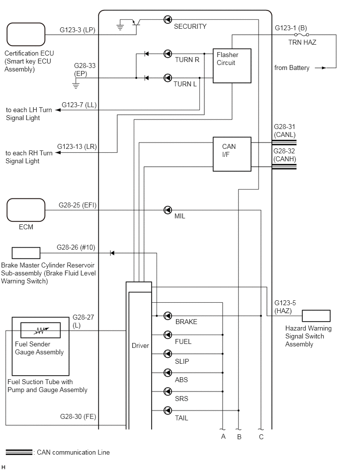
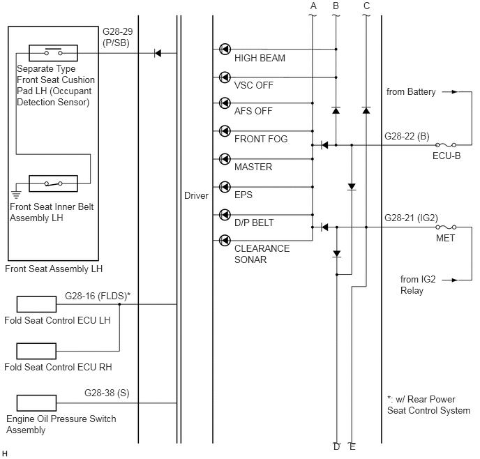
Combination Meter Sub-assembly Inner Circuit
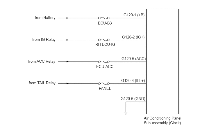
Air Conditioning Panel Sub-assembly (Clock)

Disconnect the G120 air conditioning panel sub-assembly (clock) connector.
Measure the voltage and resistance according to the value(s) in the table below.
| Symbols (Terminal No.) | Wiring Color | Terminal Description | Condition | Specified Condition |
|---|---|---|---|---|
| +B (G120-1) - Body ground | L - Body ground | Battery power supply | Always | 10 to 14 V |
| IG+ (G120-2) - Body ground | B - Body ground | Ignition power supply | Engine switch on (IG) | 10 to 14 V |
| IG+ (G120-2) - Body ground | B - Body ground | Ignition power supply | Engine switch off | Below 1 V |
| GND (G120-6) - Body ground | W-B - Body ground | Ground | Always | Below 1 Ω |
| ACC (G120-5) - Body ground | R - Body ground | Ignition power supply | Engine switch on (ACC) | 10 to 14 V |
| ACC (G120-5) - Body ground | R - Body ground | Ignition power supply | Engine switch off | Below 1 V |
| ILL+ (G120-4) - Body ground | G - Body ground | Illumination supply | Engine switch on (IG) | 10 to 14 V |
| ILL+ (G120-4) - Body ground | G - Body ground | Illumination supply | Engine switch off | Below 1 V |
If the result is not as specified, there may be a malfunction on the wire harness side.
Air Conditioning Panel Sub-assembly (Clock) Inner Circuit