RM24M0E
_58
Vehicle Interior
_059587
METER / GAUGE / DISPLAY
_0292197
METER / GAUGE SYSTEM
J
METER / GAUGE / DISPLAY METER / GAUGE SYSTEM Entire Combination Meter does not Operate
DESCRIPTION
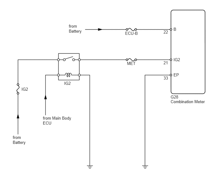
This circuit provides power to the combination meter assembly.
WIRING DIAGRAM
5.713,3.166 6.952,3.314
1.239,0.148
10
G28
5.811,2.423 6.419,2.571
0.607,0.148
10
EP
5.811,1.919 6.419,2.067
0.607,0.148
10
IG2
5.811,0.896 6.419,1.044
0.607,0.148
10
B
4.19,1.036 4.700,1.184
0.510,0.148
10
ECU-B
2.149,2.71 2.474,2.858
0.325,0.148
10
IG2
0.719,2.906 1.045,3.054
0.325,0.148
10
IG2
4.252,2.045 4.762,2.193
0.510,0.148
10
MET
1.436,3.88 2.589,4.197
1.153,0.316
10
from Main Body ECU
2.304,0.796 2.791,1.112
0.487,0.316
10
from Battery
0.427,4.523 0.914,4.839
0.487,0.316
10
from Battery
5.475,0.994 5.670,1.142
0.195,0.148
10
22
5.475,2.017 5.670,2.165
0.195,0.148
10
21
5.475,2.535 5.670,2.684
0.195,0.148
10
33
5.713,3.32 6.952,3.468
1.239,0.148
10
Combination Meter
PROCEDURE
1.INSPECT FUSE (MET, ECU-B, IG2)
a.
Remove the MET fuse from the instrument panel junction block RH.
b.
Remove the ECU-B fuse from the engine room No. 1 relay block.
c.
Remove the IG2 fuse from the engine room No. 1 relay block.
d.
Measure the resistance of the fuses.
- Standard resistance:
Below 1 Ω
OK
2.INSPECT IG2 RELAY
NG
REPLACE FUSE
2.INSPECT IG2 RELAY
a.
2.625,0.75 2.927,0.5
false
2.469,1.135 2.896,0.969
false
2.469,1.625 2.906,1.458
false
2.031,0.708 1.719,0.469
false
0.24,0.76 0.458,0.979
0.219,0.219
10
false
3
0.229,1.323 0.448,1.542
0.219,0.219
10
false
2
1.198,0.76 1.417,0.979
0.219,0.219
10
false
5
1.177,1.323 1.396,1.542
0.219,0.219
10
false
1
1.563,0.354 1.781,0.573
0.219,0.219
10
false
1
2.99,0.875 3.208,1.094
0.219,0.219
10
false
5
2.979,1.375 3.198,1.594
0.219,0.219
10
false
3
2.969,0.417 3.188,0.635
0.219,0.219
10
false
2
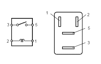
Remove the IG2 relay from the engine room No. 1 relay block.
b.
Measure the resistance of the relay.
- Standard resistance:
Tester Connection Specified Condition 3 - 5 10 kΩ or higher 3 - 5 Below 1 Ω
(when battery voltage is applied to terminals 1 and 2)
OK
3.CHECK WIRE HARNESS (COMBINATION METER - BATTERY AND BODY GROUND)
NG
REPLACE IG2 RELAY
3.CHECK WIRE HARNESS (COMBINATION METER - BATTERY AND BODY GROUND)
a.
0.06,0.018 1.397,0.202
1.336,0.184
10
Wire Harness Side:
1.538,1.024 1.826,1.192
0.288,0.168
10
G28
0.465,2.662 0.753,2.830
0.288,0.168
10
IG2
1.149,2.662 1.436,2.830
0.288,0.168
10
B
1.9,2.662 2.188,2.830
0.288,0.168
10
EP
0.567,2.072 0.567,2.656
false
0.687,2.072 1.117,2.656
false
2.02,2.072 2.02,2.656
false
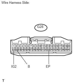
Disconnect the G28 meter connector.
b.
Measure the voltage of the wire harness side connector.
- Standard voltage:
Tester Connection Condition Specified Condition G28-22 (B) - Body ground Always 10 to 14 V G28-21 (IG2) - Body ground Ignition switch on (IG) 10 to 14 V
c.
Measure the resistance of the wire harness side connector.
- Standard resistance:
Tester Connection Specified Condition G28-33 (EP) - Body ground Below 1 Ω
OK
REPLACE COMBINATION METER ASSEMBLY
NG
REPAIR OR REPLACE HARNESS OR CONNECTOR