Home › Vehicle Interior › METER / GAUGE / DISPLAY › METER / GAUGE SYSTEM › 2013.04–2016.05
RM24M0E _58 Vehicle Interior _059587 METER / GAUGE / DISPLAY _0292197 METER / GAUGE SYSTEM C

METER / GAUGE / DISPLAY  METER / GAUGE SYSTEM  U0129  Lost Communication with Skid Control ECU  


DESCRIPTION

The combination meter assembly receives signals from the ABS and traction actuator*1 (skid control ECU) or brake actuator*2 (skid control ECU) through the CAN communication system.

DTC No. DTC Detection Conditions Trouble Areas
U0129 When either of following conditions detected:
1.

15 seconds have elapsed since engine started and IG voltage 10.5 V or more

2.

No communication with ABS and traction actuator*1 (skid control ECU) or brake actuator*2 (skid control ECU) continues for 3 seconds or more (No communication with ECM or ABS and traction actuator*1 (skid control ECU) or brake actuator*2 (skid control ECU) continues for 60 seconds or more)


·

ABS and traction actuator*1 (skid control ECU) or brake actuator*2 (skid control ECU)

·

CAN communication system


HINT:

*1: w/ VSC

*2: w/o VSC


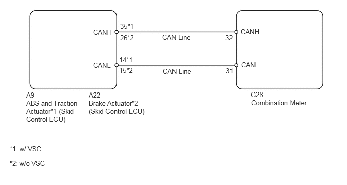
WIRING DIAGRAM

E358400E01
2.479,0.458 2.99,0.698 0.51,0.24 10 false 35*1 2.479,0.698 2.99,0.938 0.51,0.24 10 false 26*2 2.458,1.146 2.969,1.385 0.51,0.24 10 false 14*1 2.458,1.365 2.969,1.604 0.51,0.24 10 false 15*2 3.354,0.688 4.125,0.927 0.771,0.24 10 false CAN Line 1.927,0.583 2.438,0.823 0.51,0.24 10 false CANH 1.927,1.26 2.438,1.5 0.51,0.24 10 false CANL 4.656,0.698 5.167,0.938 0.51,0.24 10 false 32 4.667,1.375 5.177,1.615 0.51,0.24 10 false 31 5.177,1.865 5.688,2.104 0.51,0.24 10 false G28 5.188,2.031 6.51,2.302 1.323,0.271 10 false Combination Meter 1.833,1.875 2.344,2.115 0.51,0.24 10 false A22 1.833,2.042 3.042,2.573 1.208,0.531 10 false Brake Actuator*2 (Skid Control ECU) 0.542,1.875 1.052,2.115 0.51,0.24 10 false A9 0.542,2.042 1.635,2.677 1.094,0.635 10 false ABS and Traction Actuator*1 (Skid Control ECU) 0.198,2.979 1.125,3.219 0.927,0.24 10 false *1: w/ VSC 0.198,3.281 1.125,3.542 0.927,0.26 10 false *2: w/o VSC 4.969,0.573 5.479,0.813 0.51,0.24 10 false CANH 4.979,1.25 5.49,1.49 0.51,0.24 10 false CANL 3.365,1.385 4.135,1.625 0.771,0.24 10 false CAN Line

PROCEDURE

1.CONFIRM DTC OUTPUT
a.

Connect the intelligent tester to the DLC3.


b.

Turn the ignition switch on (IG) and turn the tester ON.


c.

Clear the stored DTCs by selecting the following menu items on the tester: Body / Combination Meter / DTC / Clear.


d.

Start the engine and wait for at least 60 seconds.


e.

Check for DTCs.

Result
Result Proceed to
DTC output A
DTC not output B


A

GO TO CAN COMMUNICATION SYSTEM

B

SYSTEM IS OK