RM24M0E
_58
Vehicle Interior
_059587
METER / GAUGE / DISPLAY
_0292197
METER / GAUGE SYSTEM
J
METER / GAUGE / DISPLAY METER / GAUGE SYSTEM Clock Display Circuit
DESCRIPTION
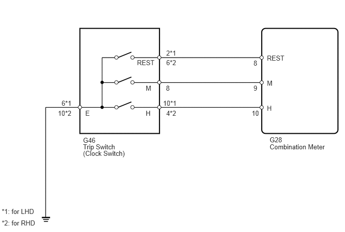
The meter's clock can be adjusted by pressing the clock switch on the trip switch.
- HINT:
-
For more information about adjusting the clock, refer to the owner's manual.
WIRING DIAGRAM
5.601,2.828 5.933,2.974
0.332,0.145
10
G28
5.545,2.165 5.974,2.311
0.429,0.145
10
H
3.387,2.063 3.817,2.208
0.429,0.145
10
10*1
3.453,2.268 3.882,2.413
0.429,0.145
10
4*2
3.028,2.268 3.295,2.413
0.267,0.145
10
H
3.448,1.745 3.877,1.890
0.429,0.145
10
8
3.028,1.745 3.295,1.890
0.267,0.145
10
M
3.453,1.016 3.882,1.162
0.429,0.145
10
2*1
3.453,1.222 3.882,1.367
0.429,0.145
10
6*2
2.846,1.222 3.293,1.367
0.447,0.145
10
REST
1.279,2.063 1.616,2.208
0.336,0.145
10
6*1
1.202,2.268 1.631,2.413
0.429,0.145
10
10*2
1.772,2.268 2.201,2.413
0.429,0.145
10
E
0.036,4.313 0.790,4.458
0.754,0.145
10
*1: for LHD
0.036,4.556 0.794,4.701
0.758,0.145
10
*2: for RHD
1.725,2.829 3.265,2.974
1.540,0.145
10
G46
1.725,2.969 3.265,3.114
1.540,0.145
10
Trip Switch
1.725,3.109 3.265,3.255
1.540,0.145
10
(Clock Switch)
5.228,2.268 5.416,2.414
0.188,0.145
10
10
5.545,1.642 5.974,1.788
0.429,0.145
10
M
5.266,1.745 5.416,1.890
0.151,0.145
10
9
5.545,1.129 5.974,1.274
0.429,0.145
10
REST
5.266,1.231 5.416,1.377
0.151,0.145
10
8
5.601,2.973 6.864,3.118
1.262,0.145
10
Combination Meter
PROCEDURE
1.READ VALUE USING INTELLIGENT TESTER (CLOCK SWITCH)
a.
Connect the intelligent tester to the DLC3.
b.
Turn the ignition switch on (IG) and the tester ON.
c.
Read the Data List according to the prompts displayed on the tester.
| Item | Measurement Item / Range (Display) | Normal Condition | Diagnostic Note |
|---|---|---|---|
| Timer Switch M on Combination Meter | Clock switch "M" signal / ON or OFF | ON: Clock switch "M" pushed
OFF: Clock switch "M" not pushed |
- |
| Timer Switch H on Combination Meter | Clock switch "H" signal / ON or OFF | ON: Clock switch "H" pushed
OFF: Clock switch "H" not pushed |
- |
| Timer Switch 00 on Combination Meter | Clock switch "00" signal / ON or OFF | ON: Clock switch "00" pushed
OFF: Clock switch "00" not pushed |
- |
- OK:
ON is displayed on the intelligent tester screen when switch is pressed.
NG
2.INSPECT TRIP SWITCH (CLOCK SWITCH)
OK
REPLACE COMBINATION METER ASSEMBLY
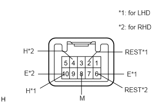
2.INSPECT TRIP SWITCH (CLOCK SWITCH)
a.
0.792,1.083 1.333,1.083
1.333,1.083 1.531,1.26
false
0.802,1.573 1.344,1.573
false
2.583,1.104 2.042,1.104
2.042,1.104 1.875,1.281
false
2.073,1.573 2.615,1.573
false
1.719,2.01 1.719,1.563
false
1.365,1.573 0.844,1.875
false
2.063,1.563 2.583,1.865
false
2.677,1.49 2.927,1.646
0.25,0.156
10
false
E*1
0.51,1.469 0.76,1.625
0.25,0.156
10
false
E*2
2.625,1.823 3.229,1.979
0.604,0.156
10
false
REST*2
1.677,2 1.927,2.156
0.25,0.156
10
false
M
2.5,0.188 3.406,0.448
0.906,0.26
10
false
*1: for LHD
2.5,0.49 3.427,0.729
0.927,0.24
10
false
*2: for RHD
0.49,1 0.74,1.156
0.25,0.156
10
false
H*2
0.542,1.844 0.792,2
0.25,0.156
10
false
H*1
2.635,1.021 3.219,1.177
0.583,0.156
10
false
REST*1
Remove the trip switch.
b.
Measure the resistance of the switch.
- Standard resistance:
for LHD Tester Connection Switch Condition Specified Condition 10 (H) - 6 (E) Clock switch "H" pushed Below 1 Ω 10 (H) - 6 (E) Clock switch "H" not pushed 10 kΩ or higher 8 (M) - 6 (E) Clock switch "M" pushed Below 1 Ω 8 (M) - 6 (E) Clock switch "M" not pushed 10 kΩ or higher 2 (REST) - 6 (E) Clock switch "00" pushed Below 1 Ω 2 (REST) - 6 (E) Clock switch "00" not pushed 10 kΩ or higher
for RHD Tester Connection Switch Condition Specified Condition 4 (H) - 10 (E) Clock switch "H" pushed Below 1 Ω 4 (H) - 10 (E) Clock switch "H" not pushed 10 kΩ or higher 8 (M) - 10 (E) Clock switch "M" pushed Below 1 Ω 8 (M) - 10 (E) Clock switch "M" not pushed 10 kΩ or higher 6 (REST) - 10 (E) Clock switch "00" pushed Below 1 Ω 6 (REST) - 10 (E) Clock switch "00" not pushed 10 kΩ or higher
OK
3.CHECK WIRE HARNESS (TRIP SWITCH - COMBINATION METER AND BODY GROUND)
NG
REPLACE TRIP SWITCH
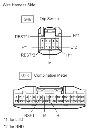
3.CHECK WIRE HARNESS (TRIP SWITCH - COMBINATION METER AND BODY GROUND)
a.
0.75,0.542 1.167,0.792
0.417,0.25
0.667,2.5 1.083,2.75
0.417,0.25
1.094,1.635 1.5,1.635
1.5,1.635 1.26,1.896
false
1.542,3.875 1.542,3.365
false
1.042,1.26 1.542,1.26
1.542,1.26 1.594,1.385
false
2.417,1.635 1.969,1.635
1.969,1.635 2.25,1.875
false
2.479,1.271 1.927,1.271
1.927,1.271 1.865,1.396
false
1.729,1.635 1.729,2.042
false
1.427,3.375 1.073,3.896
false
1.656,3.385 1.99,3.896
false
0.094,0.083 1.656,0.385
1.563,0.302
10
false
Wire Harness Side:
0.823,0.583 1.323,0.823
0.5,0.24
10
false
G46
1.375,0.563 2.26,0.802
0.885,0.24
10
false
Trip Switch
2.448,1.552 2.948,1.792
0.5,0.24
10
false
E*2
2.302,1.823 2.802,2.063
0.5,0.24
10
false
H*1
0.75,1.563 1.25,1.802
0.5,0.24
10
false
E*1
0.729,1.823 1.229,2.063
0.5,0.24
10
false
REST*2
0.74,2.531 1.24,2.771
0.5,0.24
10
false
G28
1.188,2.521 2.563,2.813
1.375,0.292
10
false
Combination Meter
0.135,4.052 1.229,4.292
1.094,0.24
10
false
*1: for LHD
0.135,4.302 1.229,4.542
1.094,0.24
10
false
*2: for RHD
0.521,1.188 1.021,1.427
0.5,0.24
10
false
REST*1
2.531,1.156 3.031,1.396
0.5,0.24
10
false
H*2
1.677,2.094 2.177,2.333
0.5,0.24
10
false
M
1.5,3.917 2,4.156
0.5,0.24
10
false
M
0.844,3.917 1.344,4.156
0.5,0.24
10
false
RSET
1.958,3.927 2.458,4.167
0.5,0.24
10
false
H
Disconnect the G46 switch connector.
b.
Disconnect the G28 meter connector.
c.
Measure the resistance of the wire harness side connectors.
- Standard resistance:
for LHD Tester Connection Specified Condition G46-10 (H) - G28-10 (H) Below 1 Ω G46-10 (H) or G28-10 (H) - Body ground 10 kΩ or higher G46-8 (M) - G28-9 (M) Below 1 Ω G46-8 (M) or G28-9 (M) - Body ground 10 kΩ or higher G46-2 (REST) - G28-8 (RSET) Below 1 Ω G46-2 (REST) or G28-8 (RSET) - Body ground 10 kΩ or higher G46-6 (E) - Body ground Below 1 Ω
for RHD Tester Connection Specified Condition G46-4 (H) - G28-10 (H) Below 1 Ω G46-4 (H) or G28-10 (H) - Body ground 10 kΩ or higher G46-8 (M) - G28-9 (M) Below 1 Ω G46-8 (M) or G28-9 (M) - Body ground 10 kΩ or higher G46-6 (REST) - G28-8 (RSET) Below 1 Ω G46-6 (REST) or G28-8 (RSET) - Body ground 10 kΩ or higher G46-10 (E) - Body ground Below 1 Ω
OK
REPLACE COMBINATION METER ASSEMBLY
NG
REPAIR OR REPLACE HARNESS OR CONNECTOR