NAVIGATION / MULTI INFO DISPLAY NAVIGATION SYSTEM Microphone Circuit between Microphone and Navigation Receiver Assembly
DESCRIPTION
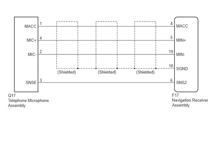
The navigation receiver assembly and telephone microphone assembly are connected to each other using the microphone connection detection signal lines.
Using this circuit, the navigation receiver assembly sends power to the telephone microphone assembly, and the telephone microphone assembly sends microphone signals to the navigation receiver assembly.
WIRING DIAGRAM
CAUTION / NOTICE / HINT
- NOTICE:
-
When replacing the navigation receiver assembly, perform vehicle contract setting (See page Audio / Visual / Telematics>G-BOOK>G-BOOK SYSTEM>REGISTRATION).
PROCEDURE
Disconnect the F17 navigation receiver assembly connector.
Disconnect the Q17 telephone microphone assembly connector.
Measure the resistance according to the value(s) in the table below.
- Standard Resistance:
Tester Connection Condition Specified Condition F17-4 (MACC) - Q17-1 (MACC) Always Below 1 Ω F17-5 (MIN+) - Q17-4 (MIC+) Always Below 1 Ω F17-19 (MIN-) - Q17-2 (MIC-) Always Below 1 Ω F17-6 (SNS2) - Q17-3 (SNSE) Always Below 1 Ω F17-4 (MACC) - Body ground Always 10 kΩ or higher F17-5 (MIN+) - Body ground Always 10 kΩ or higher F17-19 (MIN-) - Body ground Always 10 kΩ or higher F17-18 (SGND) - Body ground Always 10 kΩ or higher F17-6 (SNS2) - Body ground Always 10 kΩ or higher
OK
NG
Reconnect the F17 navigation receiver assembly connector.
Reconnect the Q17 telephone microphone assembly connector.
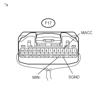
Measure the voltage according to the value(s) in the table below.
- Standard Voltage:
Tester Connection Condition Specified Condition F17-4 (MACC) - Body ground Engine switch on (ACC) 4 to 6 V
Measure the resistance according to the value(s) in the table below.
- Standard Resistance:
Tester Connection Condition Specified Condition F17-18 (SGND) - Body ground Always Below 1 Ω F17-19 (MIN-) - Body ground Always Below 1 Ω
| *a | Component with harness connected
(Navigation Receiver Assembly) |
OK
NG
Disconnect the Q17 telephone microphone assembly connector.
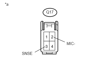
Measure the resistance according to the value(s) in the table below.
- Standard Resistance:
Tester Connection Condition Specified Condition Q17-3 (SNSE) - Q17-2 (MIC-) Always Below 1 Ω
| *a | Component without harness connected
(Telephone Microphone Assembly) |
OK
NG
Reconnect the F17 navigation receiver assembly connector.
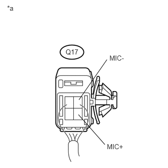
Reconnect the Q17 telephone microphone assembly connector.
Turn the engine switch on (ACC).
Connect an oscilloscope to terminals 4 (MIC+) and 2 (MIC-) of the telephone microphone assembly connector.
Check the waveform of the telephone microphone assembly using the oscilloscope.
- Result:
Result Proceed to A waveform synchronized with the voice input to the telephone microphone assembly is output A A waveform synchronized with the voice input to the telephone microphone assembly is not output B
| *a | Component with harness connected
(Telephone Microphone Assembly) |
A
B