PARK ASSIST / MONITORING ULTRASONIC SENSOR(for Rear Side) INSTALLATION
PROCEDURE

 89348A
1.INSTALL NO. 2 ULTRASONIC SENSOR RETAINER (for Back Sensor)
- HINT:
-
Use the same procedure for the RH side and LH side.
for Type A:
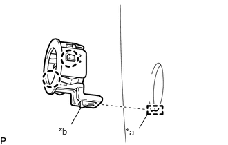
Engage the 2 claws to install the No. 2 ultrasonic sensor retainer to the rear bumper assembly.
| *a | Keyhole |
| *b | Snap |
- NOTICE:
- ·
Do not damage the rear bumper assembly with the protrusion when installing the No. 2 ultrasonic sensor retainer.
·Securely install the No. 2 ultrasonic sensor retainer so that there are no gaps between the No. 2 ultrasonic sensor retainer and surface of the rear bumper assembly.
- HINT:
-
When installing the No. 2 ultrasonic sensor retainer, align the keyhole and snap as shown in the illustration.
89341A
2.INSTALL NO. 1 ULTRASONIC SENSOR (for Back Sensor)
- HINT:
-
Use the same procedure for the RH side and LH side.
for Type A:
Engage the 2 claws to install the No. 1 ultrasonic sensor to the No. 2 ultrasonic sensor retainer.
- NOTICE:
-
Push the No. 2 ultrasonic sensor retainer from the outside of the rear bumper assembly when there is a gap between the No. 2 ultrasonic sensor retainer and the rear bumper assembly surface. In this case, do not push on the No. 1 ultrasonic sensor.
Connect the connector.
for Type B:
Engage the 4 claws to install the No. 1 ultrasonic sensor as shown in the illustration.
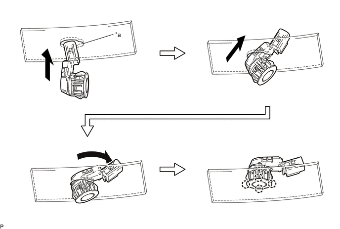
| *a | Keyhole | - | - |
- NOTICE:
- ·
Do not damage the rear bumper assembly.
·Do not damage the No. 1 ultrasonic sensor.
- HINT:
- ·
Align the keyhole and the connector of the No. 1 ultrasonic sensor as shown in the illustration.
·When pressing the No. 1 ultrasonic sensor to engage the claws, apply force perpendicular to the rear bumper assembly.
While pressing the No. 1 ultrasonic sensor from the outside of the rear bumper assembly, connect the connector.
- HINT:
-
After connecting the connector, press the No. 1 ultrasonic sensor from the outside of the rear bumper assembly.
89348
3.INSTALL NO. 1 ULTRASONIC SENSOR RETAINER (for Corner Sensor)
for Type A:
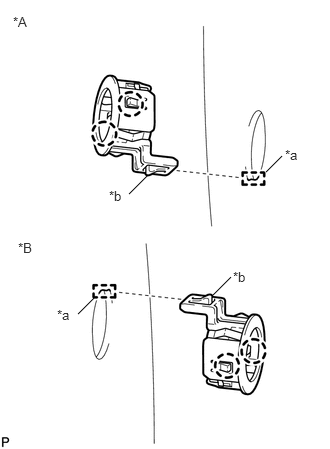
Engage the 2 claws to install the No. 1 ultrasonic sensor retainer to the rear bumper assembly.
| *A | for LH Side |
| *B | for RH Side |
| *a | Keyhole |
| *b | Snap |
- NOTICE:
- ·
Do not damage the rear bumper assembly with the protrusion when installing the No. 1 ultrasonic sensor retainer.
·Securely install the No. 1 ultrasonic sensor retainer so that there are no gaps between the No. 1 ultrasonic sensor retainer and surface of the rear bumper assembly.
- HINT:
-
When installing the retainer, align the keyhole and snap as shown in the illustration.
89341A
4.INSTALL NO. 1 ULTRASONIC SENSOR (for Corner Sensor)
for Type A:
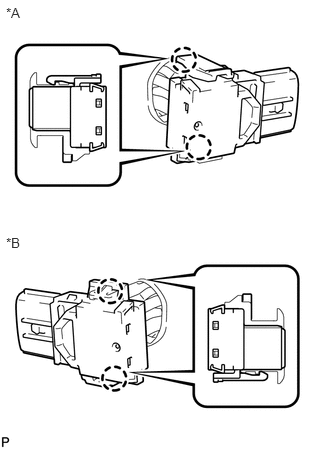
Engage the 2 claws to install the No. 1 ultrasonic sensor to the No. 1 ultrasonic sensor retainer.
| *A | for LH Side |
| *B | for RH Side |
- NOTICE:
-
Push the No. 1 ultrasonic sensor retainer from the outside of the rear bumper assembly when there is a gap between the No. 1 ultrasonic sensor retainer and the rear bumper assembly surface. In this case, do not push on the No. 1 ultrasonic sensor.
for Type B:
- HINT:
-
Use the same procedure for the RH side and LH side.
Engage the 4 claws to install the No. 1 ultrasonic sensor as shown in the illustration.
| *a | Keyhole | - | - |
- NOTICE:
- ·
Do not damage the rear bumper assembly.
·Do not damage the No. 1 ultrasonic sensor.
- HINT:
- ·
Align the keyhole and the connector of the No. 1 ultrasonic sensor as shown in the illustration.
·When pressing the No. 1 ultrasonic sensor to engage the claws, apply force perpendicular to the rear bumper assembly.
89348D
5.INSTALL ULTRASONIC SENSOR CLIP (for Corner Sensor)
for Type A:
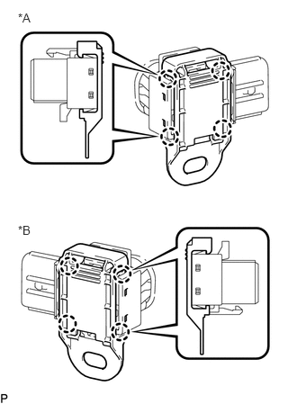
Engage the 4 claws to install the ultrasonic sensor clip.
| *A | for LH Side |
| *B | for RH Side |
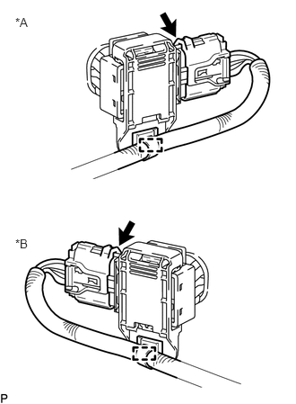
Engage the clamp.
| *A | for LH Side |
| *B | for RH Side |
Connect the connector.
for Type B:
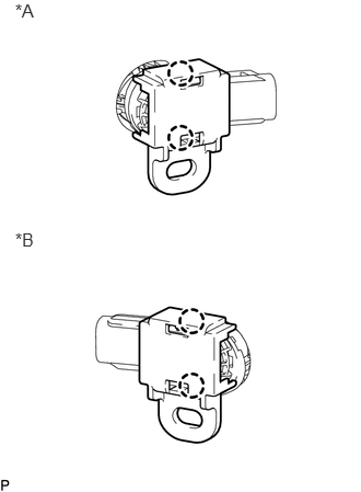
Engage the 2 claws to install the ultrasonic sensor clip.
| *A | for LH Side |
| *B | for RH Side |
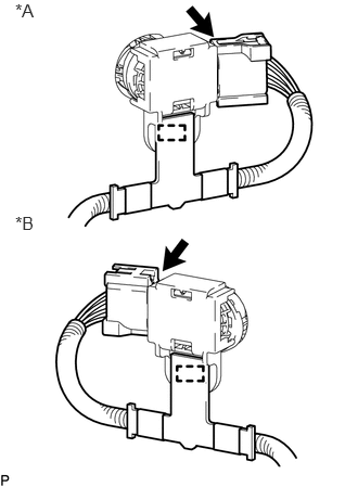
Engage the clamp.
| *A | for LH Side |
| *B | for RH Side |
While pressing the No. 1 ultrasonic sensor from the outside of the rear bumper assembly, connect the connector.
- HINT:
-
After connecting the connector, press the No. 1 ultrasonic sensor from the outside of the rear bumper assembly.
6.INSTALL REAR BUMPER ASSEMBLY