Home › Audio / Visual / Telematics › PARK ASSIST / MONITORING › TOYOTA PARKING ASSIST-SENSOR SYSTEM › 2013.04–2016.05
RM24M0E _56 Audio / Visual / Telematics _059590 PARK ASSIST / MONITORING _0292208 TOYOTA PARKING ASSIST-SENSOR SYSTEM J

PARK ASSIST / MONITORING  TOYOTA PARKING ASSIST-SENSOR SYSTEM  Vehicle Speed Signal Circuit  


WIRING DIAGRAM

for Type A
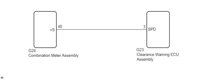

E256015E04
4.792,1.656 5.104,1.833 0.313,0.177 10 false G23 4.802,1.823 6.344,2.156 1.542,0.333 10 false Clearance Warning ECU Assembly 1,1.688 1.313,1.865 0.313,0.177 10 false G28 1,1.854 2.802,2.427 1.802,0.573 10 false Combination Meter Assembly 1.75,0.958 1.948,1.135 0.198,0.177 10 false +S 5.031,0.854 5.125,1.031 0.094,0.177 10 false 3 5.198,0.938 5.5,1.115 0.302,0.177 10 false SPD 2.031,0.844 2.208,1.021 0.177,0.177 10 false 40


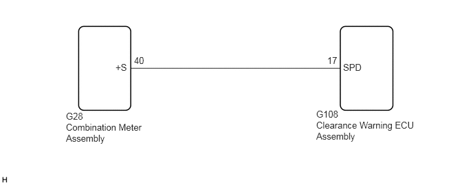
for Type B


E256015E03
4.792,1.646 5.24,1.823 0.448,0.177 10 false G108 4.792,1.813 6.333,2.146 1.542,0.333 10 false Clearance Warning ECU Assembly 1,1.677 1.313,1.854 0.313,0.177 10 false G28 1,1.844 2.229,2.417 1.229,0.573 10 false Combination Meter Assembly 1.75,0.938 1.948,1.115 0.198,0.177 10 false +S 4.958,0.833 5.167,1.01 0.208,0.177 10 false 17 5.198,0.938 5.5,1.115 0.302,0.177 10 false SPD 2.031,0.833 2.208,1.01 0.177,0.177 10 false 40


PROCEDURE

1.CONFIRM MODEL
a.

Choose the model to be inspected.

Result:
Result Proceed to
for Type A A
for Type B B


A

2.CHECK HARNESS AND CONNECTOR (SPEED SIGNAL)

B

4.CHECK HARNESS AND CONNECTOR (SPEED SIGNAL)
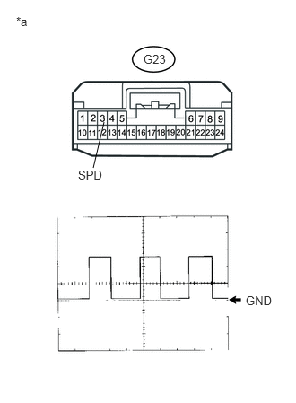
2.CHECK HARNESS AND CONNECTOR (SPEED SIGNAL)
U188785E02
1.083,1.948 1.208,1.417 false 2.854,3.406 3.219,3.563 0.365,0.156 10 false GND 0.188,0.167 0.365,0.375 0.177,0.208 10 false *a 1.667,0.604 1.948,0.76 0.281,0.156 10 false G23 0.906,1.948 1.219,2.104 0.313,0.156 10 false SPD

a.

Disconnect the G23 clearance warning ECU assembly connector.


b.

Using an oscilloscope, check the signal waveform of the combination meter assembly.

HINT:

As the vehicle speed increases, the wavelength shortens.


OK:

Waveform is as shown in the illustration.


Item Content
Terminal No. (Symbol) G23-3 (SPD) - Body ground
Tool Setting 5 V/DIV., 20 msec./DIV.
Condition Wheel being rotated

HINT:

As the vehicle speed increases, the wavelength shortens.


Text in Illustration
*a Front view of wire harness connector
(to Clearance Warning ECU Assembly)


OK

PROCEED TO NEXT SUSPECTED AREA SHOWN IN PROBLEM SYMPTOMS TABLE

NG

3.CHECK HARNESS AND CONNECTOR (CLEARANCE WARNING ECU ASSEMBLY - COMBINATION METER ASSEMBLY)
a.

Disconnect the G23 clearance warning ECU assembly connector.


b.

Disconnect the G28 combination meter assembly connector.


c.

Measure the resistance according to the value(s) in the table below.

Standard Resistance:
Tester Connection Condition Specified Condition
G23-3 (SPD) - G28-40 (+S) Always Below 1 Ω
G23-3 (SPD) - Body ground Always 10 kΩ or higher


OK

NG
REPAIR OR REPLACE HARNESS OR CONNECTOR

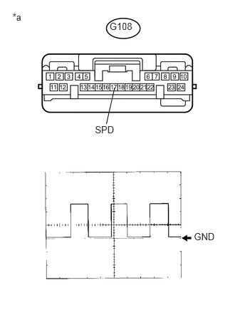
4.CHECK HARNESS AND CONNECTOR (SPEED SIGNAL)
U189984E01
2.837,3.38 3.202,3.532 0.365,0.152 10 GND 0.183,0.163 0.363,0.371 0.180,0.208 10 *a 1.602,0.299 1.961,0.456 0.359,0.158 10 G108 1.389,1.811 1.701,1.971 0.312,0.159 10 SPD 1.556,1.811 1.676,1.283 false

a.

Disconnect the G108 clearance warning ECU assembly connector.


b.

Using an oscilloscope, check the signal waveform of the combination meter assembly.

HINT:

As the vehicle speed increases, the wavelength shortens.


OK:

Waveform is as shown in the illustration.


Item Content
Terminal No. (Symbol) G108-17 (SPD) - Body ground
Tool Setting 5 V/DIV., 20 msec./DIV.
Condition Wheel being rotated

HINT:

As the vehicle speed increases, the wavelength shortens.


Text in Illustration
*a Front view of wire harness connector
(to Clearance Warning ECU Assembly)


OK

PROCEED TO NEXT SUSPECTED AREA SHOWN IN PROBLEM SYMPTOMS TABLE

NG

5.CHECK HARNESS AND CONNECTOR (CLEARANCE WARNING ECU ASSEMBLY - COMBINATION METER ASSEMBLY)
a.

Disconnect the G108 clearance warning ECU assembly connector.


b.

Disconnect the G28 combination meter assembly connector.


c.

Measure the resistance according to the value(s) in the table below.

Standard Resistance:
Tester Connection Condition Specified Condition
G108-17 (SPD) - G28-40 (+S) Always Below 1 Ω
G108-17 (SPD) - Body ground Always 10 kΩ or higher


OK

NG

REPAIR OR REPLACE HARNESS OR CONNECTOR