Home › Audio / Visual / Telematics › PARK ASSIST / MONITORING › TOYOTA PARKING ASSIST-SENSOR SYSTEM(for LHD) › from 2016.05
RM24M0E _56 Audio / Visual / Telematics _059590 PARK ASSIST / MONITORING _0292209 TOYOTA PARKING ASSIST-SENSOR SYSTEM(for LHD) J

PARK ASSIST / MONITORING  TOYOTA PARKING ASSIST-SENSOR SYSTEM(for LHD)  Clearance Sonar Main Switch Circuit  


DESCRIPTION

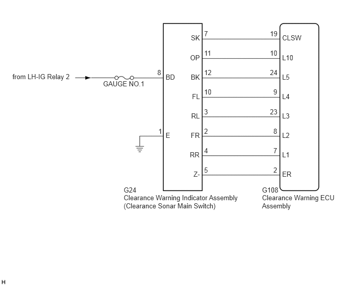
The clearance warning indicator assembly (clearance sonar main switch) is installed on the integration control and panel.

Turning this switch activates the clearance sonar system.

WIRING DIAGRAM
E256014E02
2.525,3.789 2.831,3.964 0.306,0.174 10 G24 2.525,3.948 4.939,4.280 2.414,0.332 10 Clearance Warning Indicator Assembly (Clearance Sonar Main Switch) 5.35,3.789 5.740,3.964 0.389,0.174 10 G108 5.35,3.948 6.886,4.280 1.536,0.332 10 Clearance Warning ECU Assembly 4.168,1.002 4.342,1.176 0.174,0.174 10 11 4.168,1.399 4.342,1.573 0.174,0.174 10 12 4.168,1.794 4.342,1.969 0.174,0.174 10 10 5.512,1.002 5.686,1.176 0.174,0.174 10 10 5.512,0.604 5.686,0.779 0.174,0.174 10 19 5.512,1.399 5.686,1.573 0.174,0.174 10 24 5.582,1.794 5.756,1.969 0.174,0.174 10 9 5.512,2.193 5.686,2.368 0.174,0.174 10 23 5.582,2.59 5.756,2.765 0.174,0.174 10 8 5.582,2.987 5.756,3.162 0.174,0.174 10 7 5.582,3.384 5.756,3.558 0.174,0.174 10 2 5.761,1.882 5.985,2.056 0.223,0.174 10 L4 5.761,2.28 5.985,2.455 0.223,0.174 10 L3 5.761,2.677 5.985,2.852 0.223,0.174 10 L2 5.761,3.074 5.985,3.249 0.223,0.174 10 L1 5.761,3.471 6.069,3.645 0.308,0.174 10 ER 3.382,1.486 3.595,1.660 0.213,0.174 10 BD 3.876,3.074 4.101,3.248 0.225,0.174 10 RR 3.896,2.677 4.102,2.852 0.206,0.174 10 FR 3.904,2.28 4.102,2.455 0.198,0.174 10 RL 3.921,1.882 4.102,2.056 0.181,0.174 10 FL 3.212,1.399 3.309,1.573 0.097,0.175 10 8 3.233,2.589 3.330,2.763 0.097,0.174 10 1 0.254,1.482 1.491,1.814 1.236,0.332 10 from LH-IG Relay 2 2.105,1.626 2.988,1.801 0.883,0.174 10 GAUGE NO.1 3.382,2.677 3.571,2.852 0.190,0.174 10 E 3.952,3.471 4.102,3.645 0.150,0.174 10 Z- 5.761,0.692 6.198,0.866 0.437,0.174 10 CLSW 5.761,1.089 6.177,1.263 0.416,0.174 10 L10 5.761,1.486 5.962,1.660 0.201,0.174 10 L5 4.168,0.604 4.266,0.779 0.097,0.174 10 7 4.168,2.59 4.266,2.765 0.097,0.174 10 2 4.168,2.193 4.266,2.368 0.097,0.174 10 3 4.168,2.987 4.266,3.161 0.097,0.174 10 4 4.168,3.384 4.263,3.558 0.094,0.174 10 5 3.898,0.692 4.102,0.866 0.204,0.174 10 SK 3.882,1.089 4.101,1.263 0.220,0.174 10 OP 3.896,1.486 4.102,1.660 0.205,0.174 10 BK

CAUTION / NOTICE / HINT

NOTICE:

Inspect the fuses for circuits related to this system before performing the following inspection procedure.


PROCEDURE

1.CHECK HARNESS AND CONNECTOR (CLEARANCE WARNING INDICATOR ASSEMBLY POWER SOURCE)
a.

Disconnect the G24 clearance warning indicator assembly connector.


b.

Measure the voltage according to the value(s) is the table below.

Standard Voltage:
Tester Connection Condition Specified Condition
G24-8 (BD) - Body ground Engine switch on (IG) 11 to 14 V


c.

Measure the resistance according to the value(s) in the table below.

Standard Resistance:
Tester Connection Condition Specified Condition
G24-1 (E) - Body ground Always Below 1 Ω


OK

2.CHECK HARNESS AND CONNECTOR (CLEARANCE WARNING INDICATOR ASSEMBLY - CLEARANCE WARNING ECU ASSEMBLY)

NG

REPAIR OR REPLACE HARNESS OR CONNECTOR

2.CHECK HARNESS AND CONNECTOR (CLEARANCE WARNING INDICATOR ASSEMBLY - CLEARANCE WARNING ECU ASSEMBLY)
a.

Disconnect the G24 clearance warning indicator assembly connector.


b.

Disconnect the G108 clearance warning ECU assembly connector.


c.

Measure the resistance according to the value(s) is the table below.

Standard Resistance:
Tester Connection Condition Specified Condition
G24-5 (Z-) - G108-2 (ER) Always Below 1 Ω
G24-4 (RR) - G108-7 (L1) Always Below 1 Ω
G24-2 (FR) - G108-8 (L2) Always Below 1 Ω
G24-3 (RL) - G108-23 (L3) Always Below 1 Ω
G24-10 (FL) - G108-9 (L4) Always Below 1 Ω
G24-12 (BK) - G108-24 (L5) Always Below 1 Ω
G24-11 (OP) - G108-10 (L10) Always Below 1 Ω
G24-7 (SK) - G108-19 (CLSW) Always Below 1 Ω
G24-5 (Z-) - Body ground Always 10 kΩ or higher
G24-4 (RR) - Body ground Always 10 kΩ or higher
G24-2 (FR) - Body ground Always 10 kΩ or higher
G24-3 (RL) - Body ground Always 10 kΩ or higher
G24-10 (FL) - Body ground Always 10 kΩ or higher
G24-12 (BK) - Body ground Always 10 kΩ or higher
G24-11 (OP) - Body ground Always 10 kΩ or higher
G24-7 (SK) - Body ground Always 10 kΩ or higher


OK

3.CHECK CLEARANCE WARNING INDICATOR ASSEMBLY

NG

REPAIR OR REPLACE HARNESS OR CONNECTOR

3.CHECK CLEARANCE WARNING INDICATOR ASSEMBLY
a.

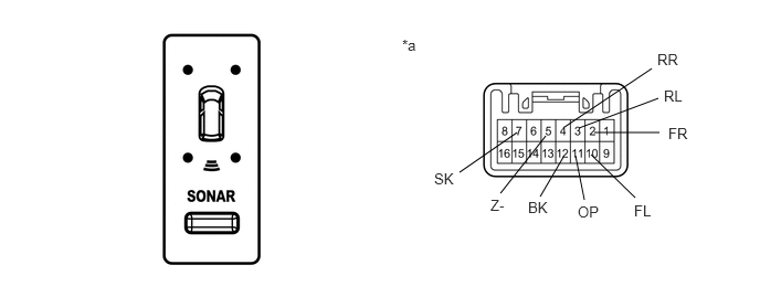
Remove the clearance warning indicator assembly, but do not disconnect the connector (See page Vehicle Interior>SEAT BELT>FRONT PASSENGER SEAT BELT WARNING LIGHT>REMOVAL).
B460062E01
4.333,1.625 4.875,1.25 false 4.719,1.823 5.146,1.281 false 5.094,1.854 5.313,1.479 false 5.51,1.885 5.427,1.469 false 5.99,1.865 5.573,1.458 false 5.323,1.198 6.146,0.646 false 5.458,1.208 6.208,0.927 false 5.604,1.25 6.219,1.25 false 3.792,0.344 4.188,0.573 0.396,0.229 10 false *a 4.094,1.604 4.49,1.833 0.396,0.229 10 false SK 4.625,1.854 5.021,2.083 0.396,0.229 10 false Z- 4.979,1.875 5.375,2.104 0.396,0.229 10 false BK 5.448,1.917 5.844,2.146 0.396,0.229 10 false OP 5.979,1.906 6.375,2.135 0.396,0.229 10 false FL 6.302,1.177 6.698,1.406 0.396,0.229 10 false FR 6.26,0.823 6.656,1.052 0.396,0.229 10 false RL 6.198,0.479 6.594,0.708 0.396,0.229 10 false RR


b.

Turn the engine switch on (IG).


c.

Measure the voltage according to the value(s) is the table below.

Standard Voltage:
Tester Condition Condition Specified Condition
7 (SK) - Body ground Clearance sonar main switch on 11 to 14 V
Clearance sonar main switch off Below 1 V
4 (RR) - Body ground Clearance warning indicator for rear right corner sensor illuminates Below 3 V
2 (FR) - Body ground Clearance warning indicator for front right corner sensor illuminates Below 3 V
3 (RL) - Body ground Clearance warning indicator for rear left corner sensor illuminates Below 3 V
10 (FL) - Body ground Clearance warning indicator for front left corner sensor illuminates Below 3 V
12 (BK) - Body ground Clearance warning indicator for rear center sensor illuminates Below 3 V
5 (Z-) - Body ground When sonar detects obstacle (buzzer sounds) Below 2 V
11 (OP) - Body ground Clearance warning indicator assembly's power indicator illuminates Below 3 V


Text in Illustration
*a Component with harness connected
(Clearance Warning Indicator Assembly)


OK

NG

REPLACE CLEARANCE WARNING INDICATOR ASSEMBLY