RM24M0E
_56
Audio / Visual / Telematics
_059590
PARK ASSIST / MONITORING
_0292212
CLEARANCE SONAR MAIN SWITCH
G
PARK ASSIST / MONITORING CLEARANCE SONAR MAIN SWITCH INSPECTION
PROCEDURE

 84970
1.INSPECT CLEARANCE SONAR MAIN SWITCH
a.
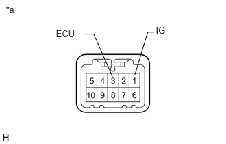
0.088,0.064 0.779,0.498
0.691,0.434
10
*a
2.368,0.379 2.642,0.628
0.274,0.248
10
IG
0.85,0.425 1.411,0.738
0.561,0.313
10
ECU
2.048,1.141 2.246,0.487
false
2.246,0.487 2.34,0.487
false
1.709,1.162 1.425,0.517
false
1.425,0.517 1.27,0.517
false
Make sure that there is no looseness in the locking part and the connecting part of the connector.
| *a | Component without harness connected
(Clearance Sonar Main Switch (Combination Switch Assembly)) |
b.
Disconnect the clearance sonar switch (combination switch assembly) connector.
c.
Check both the connector case and the terminal for deformation and corrosion.
- OK:
No deformation or corrosion.
d.
Measure the resistance according to the value(s) in the table below.
- Standard Resistance:
Tester Connection Condition Specified Condition 1 (IG) - 3 (ECU) Clearance sonar switch (combination switch assembly) on Below 1 Ω 1 (IG) - 3 (ECU) Clearance sonar switch (combination switch assembly) off 10 kΩ or higher
If the result is not as specified, replace the clearance sonar switch (combination switch assembly).