WINDOW / GLASS POWER WINDOW CONTROL SYSTEM Remote Up / Down Function does not Operate
DESCRIPTION
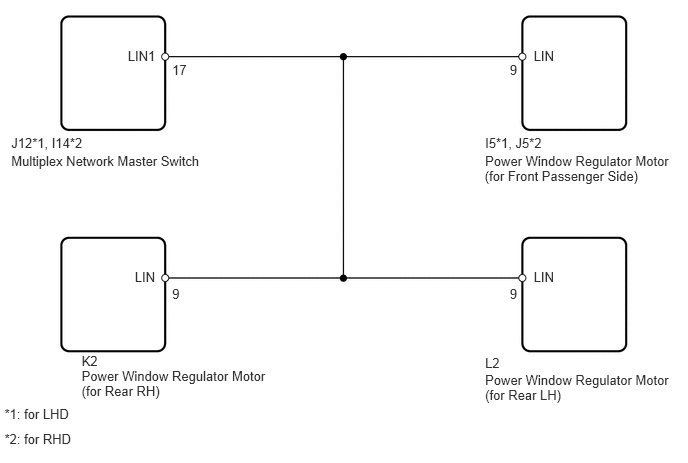
When the ignition switch is on (IG) and window lock switch is OFF, the multiplex network master switch sends remote up / down signal to each power window regulator motor via the LIN communication line.
WIRING DIAGRAM
PROCEDURE
Turn the window lock switch OFF and operate the switches on the master switch. Check that the remote UP / DOWN function operates normally.
- OK:
Remote UP / DOWN function operates normally.
NG
OK
Check that the passenger door power window and rear door power window basic function operates normally.
- HINT:
-
The "basic function" refers to whether each switch can be used to operate its own window.
- OK:
Basic function operates normally.
OK
NG
Connect the intelligent tester to the DLC3.
Turn the ignition switch on (IG) and turn the tester ON.
Select the following menu items: Body / Body ECU / Data List.
Read the display on the tester.
| Item | Measurement Item / Display (Range) | Normal Condition | Diagnostic Note |
|---|---|---|---|
| Communication Master SW | Connection status between multiplex network master switch and main body ECU / OK or STOP | OK: Connection
Stop: No connection |
- |
| Communication P-Door Motor | Connection status between power window regulator motor (for front passenger side) and main body ECU / OK or STOP | OK: Connection
Stop: No connection |
- |
| Communication RL-Door Motor | Connection status between power window regulator motor (for rear LH) and main body ECU / OK or STOP | OK: Connection
Stop: No connection |
- |
| Communication RR-Door Motor | Connection status between power window regulator motor (for rear RH) and main body ECU / OK or STOP | OK: Connection
Stop: No connection |
- |
- OK:
OK is displayed on the intelligent tester screen.
NG
OK
Disconnect the J12*1 or I14*2 switch connector.
Disconnect the motor connector for the applicable location.
Measure the resistance of the wire harness side connectors.
- Standard resistance:
for LHD Tester Connection Specified Condition J12-17 (LIN1) - Connector No. 9 for applicable location (LIN) Below 1 Ω J12-17 (LIN1) or Connector No. 9 for applicable location (LIN) - Body ground 10 kΩ or higher
for RHD Tester Connection Specified Condition I14-17 (LIN1) - Connector No. 9 for applicable location (LIN) Below 1 Ω I14-17 (LIN1) or Connector No. 9 for applicable location (LIN) - Body ground 10 kΩ or higher
OK
NG
Connect the intelligent tester to the DLC3.
Turn the ignition switch on (IG) and turn the tester ON.
Select the following menu items: Body / Master Switch / Data List.
Read the display on the tester.
| Item | Measurement Item / Display (Range) | Normal Condition | Diagnostic Note |
|---|---|---|---|
| P Door P/W Auto SW | Front passenger side power window AUTO UP / DOWN switch signal / ON or OFF | ON: Front passenger side power window switch operates (AUTO operation)
OFF: Front passenger side power window switch does not operate |
- |
| RL Door P/W Auto SW | Rear LH power window AUTO UP / DOWN switch signal / ON or OFF | ON: Rear LH power window switch operates (AUTO operation)
OFF: Rear LH power window switch does not operate |
- |
| RR Door P/W Auto SW | Rear RH power window AUTO UP / DOWN switch signal / ON or OFF | ON: Rear RH power window switch operates (AUTO operation)
OFF: Rear RH power window switch does not operate |
- |
| P Door P/W Up SW | Front passenger side power window MANUAL UP switch signal / ON or OFF | ON: Front passenger side power window switch operates (MANUAL UP operation)
OFF: Front passenger side power window switch does not operate |
- |
| RL Door P/W Up SW | Rear LH power window MANUAL UP switch signal / ON or OFF | ON: Rear LH power window switch operates (MANUAL UP operation)
OFF: Rear LH power window switch does not operate |
- |
| RR Door P/W Up SW | Rear RH power window MANUAL UP switch signal / ON or OFF | ON: Rear RH power window switch operates (MANUAL UP operation)
OFF: Rear RH power window switch does not operate |
- |
| P Door P/W Down SW | Front passenger side power window MANUAL DOWN switch signal / ON or OFF | ON: Front passenger side power window switch operates (MANUAL DOWN operation)
OFF: Front passenger side power window switch does not operate |
- |
| RL Door P/W Down SW | Rear LH power window MANUAL DOWN switch signal / ON or OFF | ON: Rear LH power window switch operates (MANUAL DOWN operation)
OFF: Rear LH power window switch does not operate |
- |
| RR Door P/W Down SW | Rear RH power window MANUAL DOWN switch signal / ON or OFF | ON: Rear RH power window switch operates (MANUAL DOWN operation)
OFF: Rear RH power window switch does not operate |
- |
| Window Lock Switch Status | Window lock switch signal / ON or OFF | ON: Window lock switch LOCK position
OFF: Window lock switch UNLOCK position |
- |
- OK:
Tester display changes normally when multiplex network master switch is operated.
OK
NG